
Last update on
- 1. Introduction
- 2. Characteristics
- 3. Connections
- 4. Standby
- 5. Saved variables
- 6. Choice of target
- 7. Safety and warnings
- 8. Protection device
- 9. Elimination
- 10. Cleaning
- 11. Technical features
1. Introduction
This manual describes the specific features of the MicroARM-A9.
For information common to programming, see the “MicroLADDER manual”. To visualize better the corresponding addresses in MicroLADDER, they appear in color, on the sides of the diagrams.
2. Characteristics
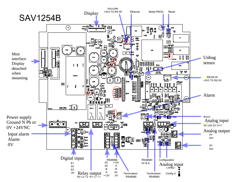
2.1 Board presentation
- ARM7 LPC1788 Cortex Processor
- 512Ko Flash (to save the monitor and the application)
- 16Mo of video RAM
- 512Ko of saved RAM extensible to 512Kw
- 1 RS232 (COM0) port with SubD9 points connector for the A version of the card and in TTL for the B version of the card. This port is available for loading or free of use.
- 1 RS232 TTL (COM1) port for loading or free of use
- 1 RS485 (COM2) port for loading or free of use with double connector and 12 Vdc supply
- 1 RS485 (COM3) port for loading or free of use with termination resistance jumper
- 1 Jtag port for the debug
- 1 Ethernet connector with 4 autonomous communication sockets (optionnal)
- 1 USB port
- 1 RTC (Real Time clock) with backup battery
- 1 EEPROM 16Ko on bus I2C (to backup variables)
- 1 connector for a 4.3 inches touch-screen graphic display (480 x 272 pixels) with backlight or a 7 inches touch-screen graphic display (800 x 480 pixels) with backlight
- 1 microSD card holder (the card must be formated in FAT32)
- Notice mArm-A9.odt 2/5
- 2 digital inputs
- 2 digital outputs with RT relay
- 2 analog inputs 0-10V or 0-20mA isolated
- 2 analog outputs 0-20mA
- 2 configuration inputs on jumper (GC2 and GC3) (under the processor)
- 1 pressure and temperature sensor mounted on the card
- 1 rest push-button (Inter 1) (located on top of the SubD9 points) picked upby jumper (J2) (located at the top left of the processor)
- 1 jumper to load programs (J1) (located at the top of the processor)
- 1 push-button for the alarm (Inter 2) (located on top of COM 3) picked up by the connector
2.2 LED signification
| L1 | Presence of a SD card (next to the microSD card connector) |
| L2 | Working order of the PLC (on right of the processor) |
| L3 | Presence of a 5V tension (on the top left of the battery) |
| L5 | Presence of a 3.3V tension (on the top left of the Ethernet connector) |
| L8 | Presence of a tension supply (next to the power pack) |
| L6, L7, L9, L10 and L11 | Ethernet (next to the Ethernet connector) |
| LD2 | Presence and use of USB port next to the USB connector |
See red circles on drawing in section 2.1
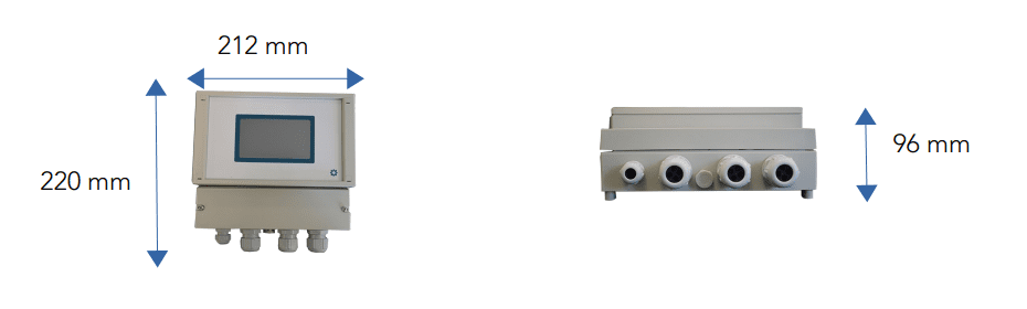
2.3 Dimensions
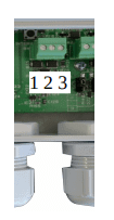
3. Connections
The following connection diagrams are in the same direction as the card presentation diagram at the beginning of this document.
3.1 Digital
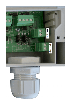
3.1.1 Digital input
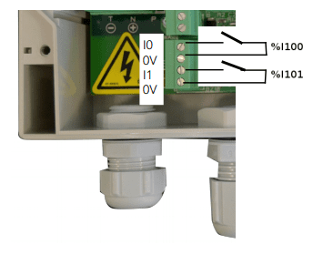
The input byte goes up linking the input to the 0 V
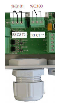
3.1.2 Digital output
This is% Q100 and% Q101. Each output has a relay with an RT contact.
See wiring on the implantation.
3.2 Analog
3.2.1 Analog input
% IW103 and IW104: analog input voltage (0-10 V = 0-10 000 points) or current (0-20ma = 0-20 000 points) configurable by jumper.
See wiring and configuration on the implantation.
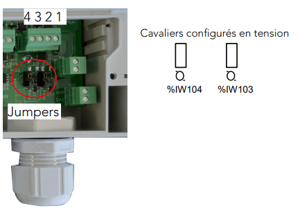
| 1 | 2 | 3 | 4 |
| EA | GND | EA2 | GND |
| %IW103 | 0V | %IW104 | 0V |
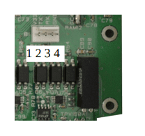
3.2.2 Analog output
%QW100 and %QW101 : outputs 0-20mA. 20 000 points = 20mA.
| 1 | GND | 0V |
| 2 | SA1 | %QW100 |
| 3 | GND | 0V |
| 4 | SA2 | %QW101 |
3.2.3 Internal board analog input
% IW100: temperature of the sensor implanted on the board in tenth of a degree.
% IW101: atmospheric pressure of the sensor implanted on the card in hectopascal.
% IW102: the power supply voltage of the card at the output of the AC/DC block or
upstream of the DC/DC block in MV.
3.3 Communication port
3.3.1 COM0 RS232
Standard broaching on DB9 (A version of the board) or see broaching on the implantation(B version of the board).
| 1 | 2 | 3 | 4 |
| V3.3 | TX0 | RX0 | 0V |

3.3.2 COM1 RS232 TTL
Standard broaching on DB9 (A version of the board) or see broaching on the implantation(B version of the board).
| 1 | 2 | 3 | 4 |
| V3.3 | TX1 | RX1 | 0V |
3.3.3 COM2 RS485
| 1 | GND |
| 2 | GND |
| 3 | B |
| 4 | A |
| 5 | 12V |
| 6 | 12V |
| 7 | A |
| 8 | B |
| 9 | GND |
| 10 | GND |
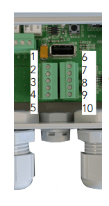
See broaching on the implantation. This port has 2 connectors with a 12 Vdc power supply. Its function is to feed 2 sensors and to communicate with it.
3.3.4 COM3 RS485
See broaching on the implantation.
| 1 | 2 | 3 |
| GND 0V | B | A |
3.4 HMI
3.4.1 Inputs
% IW0: Horizontal position of the clicked point on the screen.
% IW1: Vertical position of the clicked point on the screen.
3.4.2 Outputs
% Q0: On/off screen backlight.
% QW0: Power of the display backlight.
On the EDT screens, the backlight is not adjustable. It works properly on URT screens.
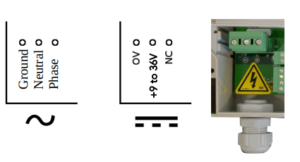
3.5 Power supply
The board can be powered either
alternating or continuous depending on the power supply that is welded to the board.
Note : the yellow warning sticker is only present on the board when the alternating (« alternatif ») current is chosen.
4. Standby
The standby is caused by the instruction:
AlimOff();
The alarm is caused by:
- Press the Wake up PB
- RTC (Time and date of the alarm must be programmed)
- By communication on the COM3 (be aware that a simple polarization of the line causes
the alarm, the 0v must be connected)
Code for programming and activating the date and time of the alarm:
Date d;
long t
t = … ;
d = timeToDate (t);
stRtcAlarm.cSeconde = d.sec;
stRtcAlarm.cMinute = d.min;
stRtcAlarm.cHeure = d.hour;
stRtcAlarm.cJour = d.mday;
stRtcAlarm.cMois = d.mon;
RtcWriteAlarm (KB_TRUE);
Code to turn off the date and time of the alarm:
RtcWriteAlarm (KB_FALSE);
5. Saved variables
There’s a saved RAM. This allows to manage histories.
6. Choice of target
In MicroLADDER, once the system code is imported, the target must be chosen. There are 4 target types for the MicroARM-A9: µArm A9 A (7″), µArm A9 A (4″3), µArm A9 B (7″), µArm A9 B (4″3).
The choice between version A and B is based on the memory that is mounted on the board. In version A, there are 16 MB of video RAM (IC10 in the top right has the reference 48LC8M16A2) and 512 KB of saved RAM (only U2 in the upper right is present). In version B there are 32 MB of video RAM (IC10 in the top right has the reference 48LC16M16A2) and 1024 KB of saved RAM (U1 and U2 in the top right are present).
The choice between 7 ” and 4 “3 is based on the size of the screen.
7. Safety and warnings
Warning
If the device is not used as per these instructions, the safety of people and equipment can be compromised. We disclaim any liability for any material damage or due to improper handling or failure to comply with the safety instructions.
The interventions on the devices must be made by staff who are competent to work on electric installations.
Before all interventions, all power supplies must be switched off. The cutting devices on the installation must be dimensioned and placed according to the standard UTE C
15-100.
For all interventions on a device installed on an electric installation, the Personal Protective Equipment (PPE) as defined by the safety regulations on the electric installations must be carried by the worker.
In the event of a failure or malfunction, the device must not be opened and must be
returned to the factory.
Observe the following pictograms:
 | Warning. On the product label this symbol means that the notice must be consulted. In this manual, this symbol indicates important information. |
 | Direct current. |
 | This device is CE approved and complies with the national and European guidelines. |
8. Protection device
Quick fuse protections must be positioned on the 24 volt continuous start feeding the PLC. These fuses will be sized according to the number of devices set in series behind the start.
9. Elimination

Old electronic devices are recyclables goods that should not be thrown into the trash can. If the device reaches the end of its life, it should be eliminated in accordance with the legal regulations in force to the recovery centres in your municipality. Elimination in the household trashes is prohibited.
10. Cleaning
For cleaning, use a clean, dry, antistatic, lint-free cloth without corrosive products.
11. Technical features
| Power supply | 9 to 36 V |
| Maximum operating altitude | 2000 m |
| Maximum operating temperature | 45°C |
| Maximum operating humidity | 70 % |