Last update on
- 1. Introduction
- 2. Specifications
- 3. Connections
- 4. Flash memory
- 5. Safety rules
- 6. Protection device
- 7. Disposal
- 8. Cleaning
- 9. Technical specifications
1. Introduction
This manual describes the specifics of the MicroARM-A13 (SAV1312 card).
For common programming information, see the “MicroLADDER manual”. To make it easier to distinguish the addresses in MicroLADDER appear in colour on the sides of the images. NC means not connected.
2. Specifications
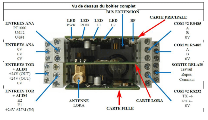
2.1 Presentation of the card
The box consists of 2 boards linked by an internal 24-pin bus. These 2 boards are not linked.
A third card can be inserted between the two main cards. This board allows the addition of LoRa / Sigfox functionality. It is also connected to the internal bus.
- Supply voltage: 10-28 VDC
- Cortex Processor LPC1768FBD
- 512 kB of internal Flash (to save the monitor and the application)
- 32 KB internal RAM
- External Flash TBC on SPI bus used by the system and the application
- 128 kB external SRAM on SPI bus
- Power supply saved by super capacity of about one week duration
- 1 RTC (Real Time Clock) internal to the processor with power supply backed up by super capacity of approximately one week duration
- 1 RS232 TTL port (COM0) for loading or free use
- 1 RS485 (COM1) and COM2) port for loading or free use
- 1 RS232 or RS485 (software configurable) port (COM2) for loading or free use
- 1 LoRa / Sigfox communication module on COM3
- 1 Bluetooth communication module
- 1 x internal temperature sensor
- 1 push button (inter3) on the front panel taken from jumper JP2
- 2 configuration jumpers (J3 and J4) free for application (coffee bean on main board)
- 2 x 24 V digital inputs
- 1 digital relay output RT 10A – 250V
- 1 analog input PT1000
- 2 analog inputs (0-10 V or 0-20 mA – 12 bits – software configurable)
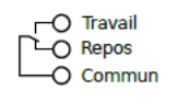
2.2 Meaning of the LEDs
| Lexan marker | Circuit diagram marker | Designation |
| PWR | L2 | Presence of 3.3V voltage |
| RUN | L1 | Operating status of the PLC |
| L1 | L3 | LED 1 bicolour free for use |
| L2 | L4 | LED 2 bicolour free for use |
2.3 Measurements
3. Connections
3.1 Digital
3.1.1 Digital inputs
%I100 to %I101 : digital inputs. The input must be connected to +24 to set the input to 1.
%I102 to %I103 : configuration inputs (soldering coffee beans on the side of the main board)
3.1.2 Digital outputs
%Q100 : RT changeover relay output.
3.2 Analog outputs
%IW100 : external temperature by connecting a PT1000 sensor. Value expressed in tenths of a degree.
%IW101 : internal temperature. Value expressed in tenths of a degree.
%IW102 à %IW103 : Analog inputs (0-10V or 0-20mA, software configurable).
3.3 Serial port
The COM0 port is present on the extension bus. It is in RS232 TTL.
The COM1 port is present on the terminal block. It is in RS485.
The COM2 port is present on the terminal block. It is in RS232 or RS485 (software configuration).
The COM3 port is internal. It allows communication with LoRa / Sigfox or Bluetooth modules (the 2 modules are exclusive).
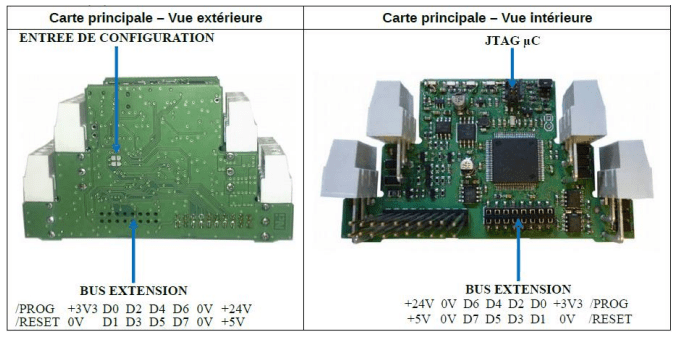
3.4 Extension
The extension bus is located on the side of the case, outside the main board. It allows the connection of extension modules.
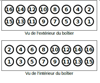
| 1 : +5 V 2 : +24 V 3 : 0 V 4 : 0 V 5 : D7 6 : D6 7 : D5 8 : D4 | 9 : D3 10 : D2 11 : D1 = COM 0 TX 12 : D0 = COM 0 RX 13 : 0V 14 : 3.3 V 15 : /RESET 16 : /PROG |
3.5 Human Machine Interface (HMI)
%IO : Push button
%QO : Green of LED 1
%Q1 : Red of LED 1
%Q2 : Green of LED 2
%Q3 : Red of LED 2
Both colours of the same LED can be controlled at the same time. The colour obtained is a mixture of the two colours
4. Flash memory
This memory is used in part by the system (calibration of analogue inputs, system variables, etc.) and the application.
The saved variables are stored in this flash memory. The %S18 bit (SAV_VARS) must be used to trigger storage.
5. Safety rules
Avertissement
Si l'appareil n'est pas utilisé conformément à ces instructions, la sécurité des personnes et de l'équipement peut être compromise. Nous déclinons toute responsabilité pour tout dommage matériel ou en raison d'une manipulation inadéquate ou d'un défaut de respect des consignes de sécurité.
Work on the devices must be carried out by employees who are competent to work on electrical installations. Before any intervention, all power supplies must be switched off. The installation’s disconnection devices must be sized and placed in accordance with the UTE C 15-100 standard.
For all interventions on a device installed on an electrical installation, personal protective equipment (PPE) as defined by the safety regulations on electrical installations must be worn by the employee.
In the event of a fault or malfunction, the unit must not be opened and must be returned to the factory.
Observe the following pictograms:
 | Warning. On the product label, this symbol means that the notice should be consulted. In this manual, this symbol indicates important information. |
 | Direct current. |
 | This device is CE approved and complies with national and European guidelines. |
6. Protection device
A short circuit protection system shall be positioned on the 24 volt continuous start supplying the PLC. These fuses shall be sized according to the number of devices in series following the feeder.
7. Disposal

Old electronic devices are recyclable products that should not be thrown away in the trash. If the device reaches the end of its life, it must be disposed of in accordance with the legal regulations in force at the recycling centres in your municipality. Disposal in household waste is prohibited.
8. Cleaning
For cleaning, use a clean, dry, antistatic, lint-free cloth without corrosive products
9. Technical specifications
| Power supply | 12 à 28 V |
| Maximum operating altitude | 2000 m |
| Maximum operating temperature | 45° Celsius |
| Maximum operating humidity | 70 % |