
Last update on
- 1. Introduction
- 2. Principle of Operation
- 3. Presentation of the Transmitter
- 4. Presentation of the SHT Soil Sensor
- 5. Presentation of the SHFT Leaf Humidity Sensor
- 6. Connecting a Sensor
- 7. Installation of the transmitter
- 8. Installation of the SHT sensor
- 9. Installation of the SHFT sensor
- 10. Programming the transmitter
1. Introduction
Please read this manual carefully and completely before installing any system.
This manual is intended to help you understand the operation of the ATH11XX transmitter and its sensors, their installation and how to set the parameters.
It is possible to contact Sinafis support by sending an email to : support.sinasens@sinafis.com
Please specify in your email your name and contact details as well as the serial number of the transmitter concerned.
1.1 Guarantee
If this product was supplied to you under a rental agreement, Sinafis guarantees the functioning of the product throughout the duration of the contract for all manufacturing defects of the product. If the product was a purchase, Sinafis guarantees the product for all manufacturing defects for a period of 6 months. In both cases, the warranty does not cover damage related to installation and / or use that does not comply with the information in this manual. Sensors whose cable is cut or torn, which are damaged, whose electrical connections are improperly installed, are not covered by the warranty. A lost, bent or broken antenna is not covered by the
warranty. The introduction of water following improper replacement of the transmitter cover or gasket is not covered by the warranty.
1.2 Sigfox Network Coverage
The Sigfox network covers 80% of French territory. It is necessary to check with Sinafis whether the location of the sensor system is covered by the network (ideally, provide the GPS coordinates of the location). It is sometimes sufficient to move the transmitter a few meters to obtain better transmission. For more information, send an email to support.sinasens@sinafis.com or contact@sinafis.com.
2. Principle of Operation
2.1 Presentation of the System
The ATH11XXS is a transmitter of soil and air temperature and humidity. It is intended for small and large agricultural holdings (wine growers, vegetable producers, fruit trees, cereals, etc.). It can also be fitted with a leaf sensor to communicate the amount of water present on the surface.“
The ATH11XXS uses Sigfox® radio technology and is powered by a 3.6V lithium battery providing long battery life that can reach several years depending on the measurement transmission frequency.
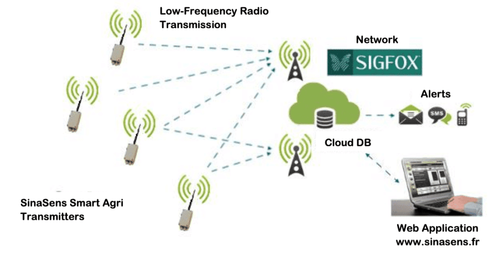
2.2. Operation Summary
Step 1
The ATH11XXS transmitter wakes up at regular intervals – generally every 2 hours – to perform the various measurements.
Step 2
The ATH11XXS transmits the measurement results by radio over the Sigfox network; the data is stored in the cloud in the SinaSens database. If alert thresholds have been defined, email notifications are sent to designated recipients.
Step 3
The user connects to the web application via a desk-top or laptop computer, a tablet or a Smartphone at www.sinasens.com to access the information of all transmitters attached to the user ID. The GPS position of each system is displayed as well as the last measurements that were recorded. A graphical rendition allows you to observe changes over time.
3. Presentation of the Transmitter
- Swiveling antenna
- Microporous vent
- 3.6V Battery
- Compression glands for sensor cables
- GPS
- LED control indicator
- Reset button
- Configuration button
- Sensor connection terminals
4. Presentation of the SHT Soil Sensor
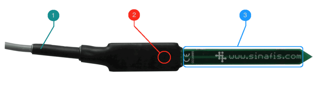
- Connection cable to be connected to the transmitter
- Temperature sensor integrated into the sensor body
- High frequency capacitive sensor (for soil humidity)
The SHT sensors allows the measurement of soil moisture and temperature. It is composed of a capacitive high frequency humidity sensor (80 MHz) and a temperature sensor integrated into the case.
The SHT sensor must only be connected to a transmitter of the SinaSens family (type ATH11XXS).
It does not need to be calibrated before use. The calibration has already been carried out in the factory during production. The sensor is completely waterproof and does not require any special maintenance. Since the capacitive sensor is sandwiched in epoxy there is no risk of damage from oxidation.
Information
All the sensors delivered are sensors identified as “Type 1” (for the first soil sensor). There are also sensors identified as "Type 2" (for second soil sensor). Type 2 sensors can be identified by a colored ring on the cable or a specific marking. It is possible to connect a "Type 1" and a "Type 2" on the same transmitter but never 2 sensors of the same type on the same transmitter!
Warning
In order for the SHT sensor to give the most accurate results, it is necessary to follow the correct procedure for placing it in the soil (see the Chapter 8).
5. Presentation of the SHFT Leaf Humidity Sensor
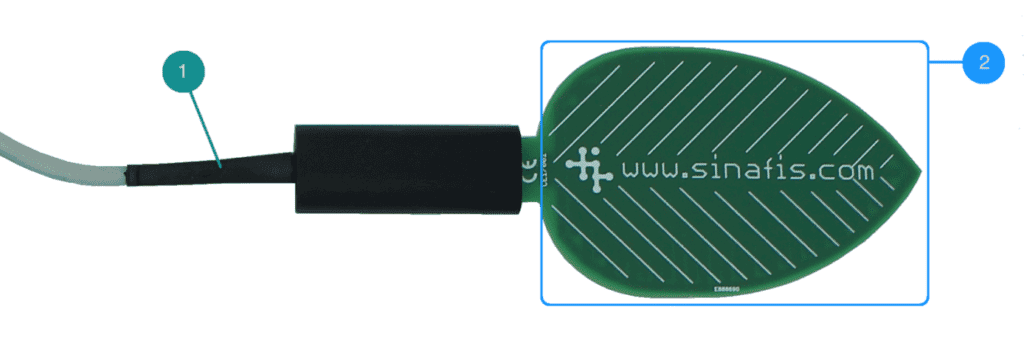
- Connection cable to be connected to the transmitter
- Medium frequency capacitive humidity sensor (for leaf)
The SHFT sensor simulates a leaf and measures the humidity on it. It is composed of a medium frequency capacitive humidity sensor with a leaf-shaped surface.
The SHFT sensor must only be connected to a transmitter of the SinaSens family (type ATH11XXS).
It does not need to be calibrated before use. The calibration has already been carried out in the factory during production. The sensor is completely waterproof and does not require any special maintenance. Since the capacitive sensor is sandwiched in epoxy there is no risk of damage from oxidation
Information
It is only possible to connect a single SHFT sensor to a transmitter.
Warning
In order for the SHFT probe to give the most accurate results, it is necessary to follow the correct installation procedure (see the Chapter 9).
6. Connecting a Sensor
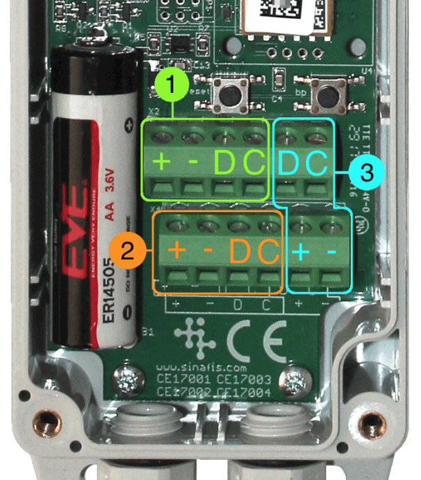
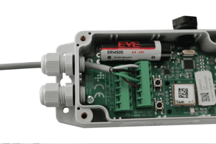
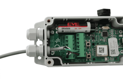
- Open the box and locate the connection terminal blocks. There are 3 possible locations to connect a sensor (SHT or SHFT). There is no placement order. It is possible to choose either position 1, 2 or 3 without any impact on the operation of the product.

- Loosen the cable gland through which the sensor cable must pass.
- Pass the cable through the cable gland.

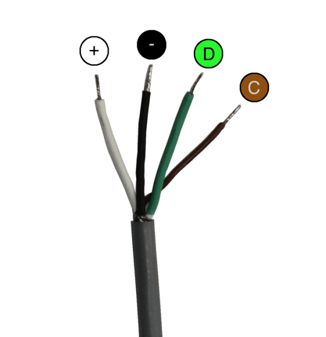
- Connect the sensor to the terminal block in the configuration of your choice, as follows:
- White-> terminal +
- Black -> terminal –
- Green -> terminal D
- Brown -> terminal C
- Moderately tighten the cable gland to ensure tightness.
- Check that the antenna is FIRMLY SCREWED onto the box.
Tip
In areas where there are high winds, you can put a drop of superglue on the outside of the antenna connector threads to secure the antenna and avoid a “helicopter” effect.
7. Installation of the transmitter
The transmitter uses the Sigfox network and like any radio system it is necessary to respect a few simple rules to obtain the best performance:
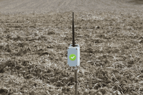
FIRMLY ANCHOR a stake in the ground and place the SinaSens at its upper end. Check that the
mounting height allows the positioning of the sensor in the ground.
- Attach the transmitter and orient the antenna VERTICALLY.
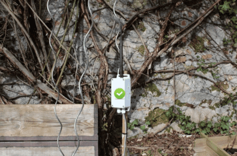
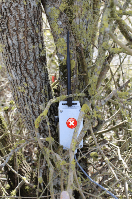
- MAKE SURE that the antenna is as unimpeded as possible. Ideally, there should be no obstacles within 30cm of the antenna.
- For vertical installation, make sure the cable connections are facing DOWN, on the bottom of the transmitter.
- If the transmitter is placed horizontally, the antenna must be oriented VERTICALLY.
- ALWAYS MAKE SURE that the antenna is firmly screwed on. Otherwise, if exposed to strong winds, it may come unscrewed and fly away. (Think of the seed pods for Maple trees.)
8. Installation of the SHT sensor
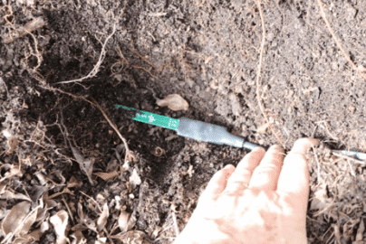

To obtain the best results for measuring humidity, it is imperative that the sensor part 3 is COMPLETELY in contact (upper and lower face) with the soil. The most effective solutions are the following:
- If the soil is free of rocks and pebble, dig a hole to the depth that you want to measure the temperature and humidity.
- Insert the sensor horizontally into the wall of the hole all the way to the cable.
- Fill the hole.
If the soil is dry or sandy, you will need to use the following procedure to ensure that there is good contact:
- Make a hole in the ground to the desired measuring depth.
- Make a dry mudball by mixing soil (without any rocks, pebble, roots, etc.) from the hole at the level you want to measure with a little water.
- Place a bit of the mudball at the bottom of the hole.
- Position the sensor horizontally on this bit of mudball.
- Cover the sensor with the rest of the mudball, pressing down firmly.
- Refill the hole, tamping down the soil as you go.
- The first few measures will mainly reflect the humidity of the mudball. After a few hours, or even a few days depending on the volume of the mudball, the measurements will correspond to the soil moisture.
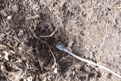
For the soil temperature measurement, you must remember that the temperature sensor 2 is located on the body of the sensor. It is therefore necessary that the body of the sensor is also placed in the ground.
Simply planting the probe vertically in the ground with the body outside does not measure the temperature of the soil but only that of the body exposed to free air and sunlight.
In conclusion, for a correct measurement of soil humidity and temperature, the probe must be completely buried in the soil with a complete contact of the sensor part 3 with the soil.
9. Installation of the SHFT sensor
To obtain the best results for measuring leaf humectation, make sure that after installation nothing is touching the sensor 2. Any element (support, branch, etc.) in contact with the sensitive part (the leaf-shaped panel) will modify the value read.
INSTALLATION SUGGESTIONS:
Use an L-shaped support made of iron or aluminum or a piece of reinforcing bar.
- Fix the vertical part of the support on a stake or a post (that of the transmitter for example).
- Secure the body of the sensor to the horizontal end of the support, making sure that the sensitive part is clear. It is possible to use wire clamps or the zip ties to attach the sensor to the support.
- Twist the support to give a slight inclination to the SHFT sensor; this will prevent water from pooling on the surface.
- Fix the sensor body to a branch of the vine or fruit tree using flexicord.
MAKE SURE that there is nothing touching the surface of the sensor. During the growing season, it may be necessary to reposition the sensor as leaves develop. The measurements will be more relevant to detect rain, dew, snow or even ice.
10. Programming the transmitter
10.1. The different modes
The transmitter has 8 configurable transmission modes :
- 15 minutes
- 30 minutes
- 1 hour
- 2 hours
- 4 hours
- 8 hours
- 12 hours
- 24 hours
The transmitter has a test mode reserved for laboratory measurements and a sleep mode.
Each of the 8 transmission modes can be identified by flashes on the red LED indicator built into the product.
The different modes are identified as follows:
- 1 flash for mode 1
- 2 flashes for mode 2
- etc ..
The test mode can be identified by the emission of very fast flashes on the LED.
Warning
Don't use test mode.
The sleep mode is identifiable by the emission of a sequence of fast and slow flashes.
10.2. Exemple :
Activate Mode 4 for a transmission every 2 hours:
- Open the box by unscrewing the 4 captive screws of the cover.
- Push and hold down the BP button. CONTINUE TO HOLD while completing step 3.
- Push and release the RESET button. After a few seconds, the transmitter will cycle through the modes. The LED will flash for each mode as it cycles through the modes.
- Release the BP button when the SinaSens displays mode 4 (emission of a series of 4 rapid flashes).
- After ten seconds or so, the transmitter confirms that it is in mode 4 (emission of a series of 4 flashes). Replace the cover on the case. CHECK AND CONFIRM that the watertight seal is in place while re-tightening the screws.
10.3 Notes on the modes
During configuration, the modes change cyclically as shown in the following figure as long as the BP button has not been released. If the desired mode has been passed, just keep the BP button pressed until the desired mode reappears or repeat the previous procedure in step 2.
10.4 Notes about the GPS positioning
The transmitter first searches for its GPS position after a Reset (a brief push on the RESET button), and then approximately every 24 hours. The search for the GPS position takes a maximum of 2 minutes so as not to exhaust the battery.
The GPS position can only be determined if the transmitter has a clear sky. It will be practically impossible to obtain the position in a hangar, in a building, in a basement, etc.
The installation of the SinaSens under a wooden shelter or in a greenhouse does not generally pose a problem for the reception of GPS signals.
The presence of an environment made of concrete, stone, sheet metal, etc. is generally detrimental to the good transmission or reception of radio waves both for the Sigfox network and for the GPS.