
Last update on
- 1. Introduction
- 2. Safety instructions
- 3. Product description
- 4. Product installation
- 5. GUI (Graphic User Interface) instruction
- 6. Routine maintenance
1. Introduction
1.1 Targeted reader
Only professional electricians or qualified personnel can carry and install this device.
The operator must be fully acquainted with the structure and the operating principle of the energy storage system.
The operator must be fully acquainted with these operating instructions.
The operator must be fully acquainted with the local regulations of the project.
1.2 How to use this document
Read this manual before installing the AEH cabinet.
Keep this manual within reach at all times.
The content of this manual will be periodically updated or revised if necessary. However, deviations can not be excluded.
2. Safety instructions
lnverter installation and service personnel must be trained and familiar with the general safety requirement when working on electrical equipment. Installation and service personnel should also be familiar with the local laws and regulations and safety requirements.
- Read this manual carefully before operation. The equipment will not be under warranty if failing to operate according to this manual.
- Operation on the AEH must be for qualified electrical technicians only.
- When AEH is operating, don’t touch any electrical parts except for the touch screen.
- All electrical operations must comply with local electrical operation standards.
- Warranty service for the AEH does not contain module maintenance.
- Permission from the local utility company is required before installing the Energy Storage system and only professional personnel are qualified for the operation.
2.1 Installation
Proper installation requires following all the instructions in the user manual involving transportation, mounting, wiring and commissioning. SIREA does not cover warranty for the AEH damage due to failing to use it properly. The protection level of the AEH is IP55, which is designed for indoor installation.
Please refer to chapter 4 for installation instruction. The installation location must be dry, including no expected condensation. The AEH is only for use in a closed electrical operating area.
Warning
Risk of fire hazard. Suitable for mounting on concrete or other non-combustible surfaces only.
2.2 Operator
lnverter installation and service personnel must be trained and familiar with the general safety requirement when working on electrical equipment. Installation and service personnel should also be familiar with the local laws and regulations and safety requirements.
2.3 Inspection and storage
The AEH should be carefully checked before signing the document from the transportation company. Check the received items against the delivery note, and if there is any defect or damage, immediately notify the transportation company. If necessary, you can seek help from SIREA Customer Service department.
Warning
AEH can only be stored when it is stopped and ail the : doors are closed in a dry room to protect the internal circuits against dust and moisture.
2.4 Transportation
Transportation should follow the transportation methods described in the user manual. The AEH’s weight and center of gravity should be taken into account during transportation. The center of gravity is marked on the box.
Danger
During transportation, lifting equipment and personnel must be qualified. The AEH should be placed vertically and the inclination cannot be more than 10 degrees. lt is not allowed to place the AEH upside down or transport in a horizontal position. Incorrect lifting and transportation can lead to serious injury, property loss and damage to the AEH.
2.5 Repair and maintenance
Repair and maintenance can only be carried out after disconnecting the DC and AC for at least 5 minutes.
Only professional technical personnel are qualified for the operation.
2.5.1 Disconnecting switches
Disconnect the DC switch and AC switch, and make sure the AEH will not be connected accidentally. Ensure the AEH is totally disconnected with no voltage by testing with a multimeter. Although the DC and AC switch has been disconnected, there is still voltage in some components, for example capacitors. Hence, the repair or maintenance operation can only proceed at least 5 minutes after the disconnection.
2.5.2 Maintenance and modification
Only personnel with SIREA authorization are qualified for the maintenance and modification. And to ensure persona! safety, use original accessories provided by the manufacturer only. Otherwise, electrical safety and EMC might not comply with the required standard.
2.5.3 Function and safety parameters
Don’t change the parameters of the AEH without authorization from the local utility and SIREA. Otherwise, it might lead to injury or equipment damage and the warranty of the AEH will be voided.
Warning
Risk of electric shock, energy storage timed discharge. Electrical shock danger exists in the capacitor; the caver shall be: moved at least 5 minutes later after all powers are disconnected.
2.6 Inverter EMC and noise level
Electromagnetic compatibility (EMC) is the requirement for electrical equipment that it can operate normally in the electromagnetic environment and does not cause unacceptable environmental impact itself.
- Anti-interference property from internal components
- Anti-interference property from outside
- Electromagnetic emission impact on the environment
lnverter may generate some noise and electromagnetic radiation during operation. According to EMC emission and noise level, AEH should be used in industrial environments. Hence, ail personnel should not stay long near the AEH.
2.7 Important notes
Static electricity can cause damage to the AEH
Electrostatic discharge may cause unrecoverable damage to AEH internal components. When operating the AEH, the operator must comply with anti-static protection norms!
Restriction
The AEH cannot be directly used to connect the life support equipment and medical equipment.
Precautions
Make sure installation tools or other unnecessary items are not left inside the AEH before starting up.
Maintenance notice
Maintenance can only be carried out after the AEH is totally discharged.
3. Product description
3.1 Concerned references
| Reference | Product name |
|---|---|
| 2EN02-00700 | AEH 10 |
| 2EN02-00710 | AEH 15 |
| 2EN02-00101 | AEH 15 (old version) |
| 2EN02-00711 | AEH 20 |
| 2EN02-00709 | AEH 20 (old version) |
| 2EN02-00100 | AEH 20 (old version) |
| 2EN02-00200 | AEH 30 |
| 2EN02-00300 | AEH 40 |
| 2EN02-00600 | AEH 60 |
| 2EN02-00712 | AEH 80 |
| 2EN02-00601 | AEH 80 (old version) |
| 2EN02-00602 | AEH 100 |
| 2EN02-00603 | AEH 120 |
| 2EN02-00604 | AEH 140 |
3.2 Specifications
3.2.1 Dimensions
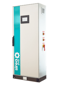 | 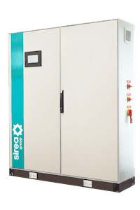 | 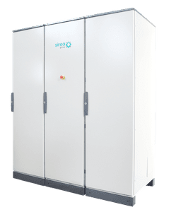 |
| AEH up to 20 210 x 60 x 80 cm | AEH up to 40 210 x 120 x 80 cm | AEH over 40 210 x 180 x 80 cm |
3.2.2 Common technical specifications
- PV Input max voltage: 1000V
- Battery nominal input: 48V
- PV max. current / input: 25A
- Max. solar rate: 97,7%
- Max battery rate: 97,8%
- lngress Protection: IP55
- Overvoltage category: Type II for AC output / Type Il for DC input
- Mains connection: Permanent connection
- Transformer info: With isolating Transformer
3.2.3 Technical specifications per model
| AEH 10 | AEH 20 | AEH 30 | AEH 40 | AEH 60 | AEH 80 | AEH 100 | |
|---|---|---|---|---|---|---|---|
| AC output | 10 kW | 20 kW | 30 kW | 40 kW | 60 kW | 80 kW | 100 kW |
| PV max. input | 2 x 7.5 kWp | 2 x 15 kWp | 3 x 15 kWp | 4 x 15 kWp | 6 x 15 kWp | 8 x 15 kWp | 10 x 15 kWp |
| MPPT voltage range | 220 – 850 V | 450 – 850 V | 350 – 850V | 450 – 850 V | 450 – 850 V | 450 – 850 V | 450 – 850 V |
| Maximum charging / discharging current | 3 x 400 VAC + N | 400 VAC tetra | 400 VAC tetra | 400 VAC tetra | 400 VAC tetra | 400 VAC tetra | 400 VAC tetra |
| Weight (without battery) | 350 kg | 350 kg | 350 kg | 450 kg | 550 kg | 590 kg | 640 kg |
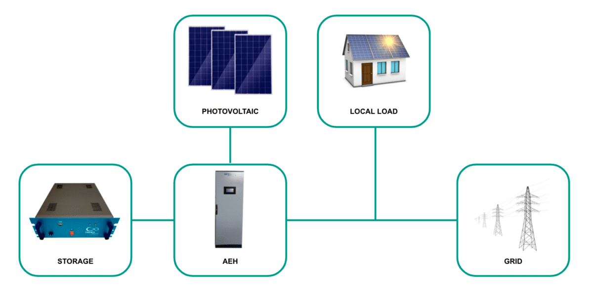
3.3 Energy storage system
AEH cabinet are designed for energy storage and photovoltaic system, it converts DC current generated by PV modules into DC for battery bank and AC current and feed it into the load/grid. DC for battery can also feed into the load/grid.
Structure of a typical energy storage system is shown as below :
3.4 Circuit diagram of the inverter
AEH inverter converts DC current generated by PV modules into DC current on bus, then into DC current to charge battery or AC current, it can also convert DC current from battery to AC current. Then the AC current is filtered into sine wave electricity and fed into the grid through a medium-voltage isolating transformer.
The circuit diagram is as below:

3.5 The layout of the main components
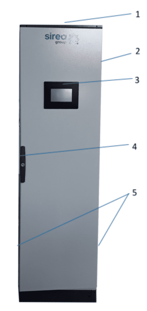
| Area | Comments |
|---|---|
| 1 | Fan Fan for heat extraction |
| 2 | Cabinet IP55 IK10 cabinet |
| 3 | Touch screen Operation information display and control command |
| 4 | Lock Lock to open door with double bar key |
| 5 | Ventilation grid Grid for fan aspiration |
3.6 Operation mode
There are several operation modes of the AEH.
3.6.1 On-grid mode
- AEH connected to PV modules on DC side and grid on the AC side;
- AEH connected to AC transducer placed on AC circuit where auto-consumption is needed;
- Batteries started.
- Every switches and breakers on:
- Transducer measure energy flux and take energy from PV and battery if available.
- If PV greater than consumption, PV supply consumption and charge batteries
- If PV is lower than consumption, PV and batteries supply consumption, if power consumption is higher than PV and batteries capacities, grid supply also.
- When the battery level is low, they go to standby mode, PV and grid supply consumption..
3.6.2 Off-grid mode
- AEH connected to PV modules on DC side and grid on the AC side;
- AEH connected to AC load and AC supply (grid or genset)
- Batteries started.
- Every switches and breakers on:
- If PV greater than consumption, PV supply consumption and charge batteries
- If PV lower than consumption, PV and batteries supply consumption, power consumption can’t be greater than nominal power of cabinet
- When the battery level is low, the cabinet is connected to the grid by contactor or start genset to supply loads and charge batteries.
- If PV greater than consumption, PV supply consumption and charge batteries
Information
When the ambient temperature is too high, it is normal that the AEH reduces the output power. However, if this frequently happens, check the cooling surface of the AEH or place the AEH in a better ventilation condition place. If the AEH fan is dirty, please clean the fan, if there is a problem with the AEH internal electrical, please seek help from professional services.
3.7 Battery setting
Battery is an important part of the energy storage system, strict protection is needed in the whole operation process. Protection threshold needs to be set on AEH to ensure safe operation of battery, parameters including: battery quantity and unit quantity, capacity, charge current, discharge current, over voltage protection, under-voltage protection and so on. Battery parameter setting need to be done by professional personnel. lmproper setting of the battery will affect the normal operation.
3.8 Protection
3.8.1 Anti-islanding
When the local power grid shut down due to malfunction or maintenance of equipment, the AEH will be physically cut off the connection to the grid, in order to protect operating personnel working in the electricity grid, and the cabinet is in compliance with the relevant standards.
3.8.2 Lightning protection
Cabinet lightning protection module has the DC / AC side lightning over voltage protection to avoid the AEH from being damaged. More protection features, please refer to chapter 6.3.
3.9 Storage
If there is a long time before installation or operation, the AEH cabinet should be stored appropriately.
- The packaging should be restored toits original state;
- Retain the desiccant in the packaging.
- The AEH can only be stored when it is stopped and ail the doors are closed in a dry room to protect the internai circuits against dust and moisture.
- Operating temperature range: -10~55 °C
- Operating relative humidity range:0 %~90%
- Max. altitude:2000 m
Warning
Strictly prohibited storage without packing! Avoid storage in direct sunlight and keep upright and no stacking on top of the crate.
4. Product installation
4.1 Installation condition requirements
To ensure normal operation of the machine, the installation environ mentis required as follows:
- The ingress protection of AEH is IP55. Moreover, as this product is an electronic equipment, it shall not be placed in humid environment;
- lnstall indoors and avoid sunlight and rain;
- Ventilation of the room shall be good;
- The installation environment shall be clean;
- As some noise will be produced in operation, this equipment shall be installed far from residential quarters;
- The installation ground shall be even enough, and firm enough to support the weight of cabinet;
- The installation position shall be convenient for maintenance;
- Ambient temperature range: 0°c
- Appropriate space shall be reserved for the machine to ensure ventilation and cooling.
We suggest AEH is installed in the distribution room. The floor, wall clearance, Ventilation equipment and precaution should be designed by professional personnel and satisfy the following requirements.
4.1.1 Foundation requirement
AEH is required to install on even ground with fire-retardant material as the surface or channel steel support structure, and sag or tilt ground is prohibited. The foundation shall be solid, safe and reliable. The foundation shall be capable of bearing the load of the AEH. lts load bearing ability shall be concerned throughout the installation place selection.
4.1.2 Clearance space
During installation of the AEH, appropriate space shall be left to the wall or other equipment, in order to satisfy the requirements on narrowest maintenance channel, emergency access and ventilation.
ln front of the installation place of AEH, a space of 1m or more shall be ensured, the back 0.1m or more, the side 0.1m or more, the top 0.6m or more to ensure easy installation, cooling and maintenance.
4.1.3 Cable trench
The cable connection of AEH adopts bottom inlet and bottom outlet. Cable trenches are recommended. The cable trenches are often designed and constructed by the construction side based on relevant standards, with the equipment weight and dimensions required to be considered. Good electrical connection is needed between different cable trenches and GND terminais.
4.1.4 Wiring specification
Cables in the AEH can be classified into either power cables or data cables. ln cabling, the power cable shall be kept far away from, and the cable shall be kept in right angle at cross. The cable shall be as short as possible, and an appropriate distance shall be kept to the power cable.
The power cable and data access shall be placed in different cable trenches respectively to avoid lengthy routing between the power cable and other cables, so as to reduce the electromagnetic interruption caused by sudden change of the output voltage. The distance among the power cable and data access shall be more than 0.1m. When the cables are crossed, the cross angle shall be 90 degrees, while the distance can be reduced appropriately.
4.1.5 Ventilation requirement
ln operation, AEH will produce a lot of heat. When ambient temperature is too high, the electrical property of the equipment may be affected, the equipment may even be damaged. Therefore, the heat release shall be fully considered in designing the contrai room to ensure operation of the equipment in high efficiency.
4.1.6 Ventilation environment
To satisfy the ventilation requirement of AEH, its installation environment shall meet the following conditions:
- lnverter shall be prevented from being installed in the place of poor ventilation condition and insufficient air flow;
- The air inlet shall have enough air supplementation.
4.1.7 Ventilation equipment
To ensure safe and reliable operation of the equipment, the ambient temperature must be within the permission range 0°C~55°(, therefore, appropriate ventilation devices must be equipped with to release the heat generated by the equipment.
There must be ventilation equipment inside the distribution room to ensure release of the waste heat generated by the AEH from the equipment, and allow for maximum ambient environment temperature. This can be realized from installation of exhaust devices; Another fan can be added at the air duct outlet to exhaust the air out and ensure balanced pressure; The direction of the air outlet shall be selected according to the local actual wind direction; Pay attention to the dust-proof measures and waterproof design at the air inlet and outlet; If more air ducts are required, its dimensions shall be designed by the professionals according to the air output a mount.
4.1.8 Other protections
According to EMC requirement and noise level, the AEH shall be installed in industrial environment.
4.2 Tools and spare parts required for installation
- Hoisting crane
- forklift or fork lift truck (with the capacity for bearing the weight of the AEH)
- Torque wrench
- Screwdriver
- Wire stripper
- Terminal crimping machine
- Megger and multimeter
4.3 Transportation of packaged whole machine
This cabinet is transported as an integrated unit, and the user can hoist it from the bottom with a forklift, or move it with a hoisting crane or crane.
- The cabinet is integrated and cannot be disassembled either in transportation or installation. Any fault attributed to modification unauthorized by SIREA is beyond the quality assurance.
- ln movement, tilt, violent shake or sudden force upon the AEH shall be prevented, such as sudden down of lifting.
- Please read carefully the labeled parameters to select an appropriate transportation means and storage place. We suggest the user make use of a forklift to move the cabinet if possible.
Tip
Before the AEH is moved to the designated place, we suggest to lay the DC input cable and AC main power supply cable. As these cables are relatively thick, they are hard to be cabled after the AEH is installed.
4.4 Electrical installation
4.4.1 Input and output requirements
Danger
There is a danger of electrical shock of high voltage in AEH's operation; only electricians of professional skills can operate. All connections with this equipment shall be done under non-voltage state : The AEH may be damaged if the input or output terminal is incorrectly plugged. Failure of acting upon this information may cause serious personal injury or significant property loss even to death.
| Model | Cable (Cu) | Cable Diameter Requirements (mm2) | Aperture |
|---|---|---|---|
| AEH 20 | Grid Phase A | 1 input cables with each at least 6 mm2 | ct > 8,20N*m |
| AEH 20 | Grid Phase B | 1 input cables with each at least 6 mm2 | ct > 8,20N*m |
| AEH 20 | Grid Phase C | 1 input cables with each at least 6 mm2 | ct > 8,20N*m |
| AEH 20 | NWire | 1 input cables with each at least 6 mm2 | ct > 8,35N*m |
| AEH 20 | Earth Wire | More than 16 mm2. Green and yellow is recommended | ct > 8,20N*m |
| AEH 20 | Transducer Wire | 0.75 mm2, shielded Twisted pair is recommended | – |
| AEH 20 | Ethernet | Category 5 FTP/UTP or more is recommended | – |
Battery
The positive and negative highest voltage of the battery shall not exceed 60V, otherwise, the equipment will be in over-voltage protection state, and cannot work normally.
Three-phase grid
lnverter will continuously inspect whether the grid satisfies the grid connected conditions. The following is the grid limit for satisfaction of local Grid connected Conditions (requirements in different countries may vary, the value can be set up and please refer to local grid connected regulations for details), and the grid is a three phase grid. Meanwhile, it shall be permitted by the local power supply department before installing Grid-connected inverted power.
| Model | Limit | Comment |
|---|---|---|
| AEH 20 | Grid Voltage Limit | 184 – 265 Vac per phase |
| AEH 20 | Grid Frequency Limit | 45Hz-5 5Hz/5 5Hz-65Hz |
4.4.2 DC batterie side wiring
Danger
When connecting the AC grid, cut off the circuit breaker at the AC side to ensure that the AC wire connecting to terminals has no electricity.
Specific procedures are as follows:
- Cut off the distribution circuit breaker at the DC side, and ensure that no voltage on the wire at DC side.
- Determine the positive and negative with a multimeter
- Connect the positive of the battery to the “DC +”of DC input
- Connect the negative of the battery to the” DC-” of DC input
- Please be sure that all wirings are fastened.
4.4.3 AC side wiring
Danger
The positive and negative of the battery shall not be connected in reverse. A multimeter shall be used to determine the polarity first, and then connect into the corresponding input ends of the AEH.
Connect AC grid:
- Cut off the circuit breaker at AC side, to ensure that the AC wire connecting to terminais has no electricity. Confirm it with a multimeter.
- Connect phase on grey terminal XP 2/3/4
- Connect neutral on blue terminal XP1
- Please confirm that the wiring is fastened
4.4.4 Earthing
Cabinet must be earthing well for safety; Please make sure of the connection between PE in power distribution cabinet and PE copper in the AEH good; and make sure the earthing cable more than 16mm2 and the earthing resistance must satisfy the demand of IEC standard.
4.4.5 DC PV modules side wiring
Specific procedures are as follows:
- Cut off the PV module string at the array with MC4 connectors, and ensure that no voltage on the wire at DC side.
- Determine the positive and negative with a multimeter
- Connect the positive of the PV to the PV terminals (XPV2/4/6/8)
- Connect the negative of the PV to the PV terminals (XPV1/3/5/7)
- Please be sure that ail wirings are fastened.
4.5 Communication
AEH can be connected to external transducer, in this case connect a cable to XC1/2 terminal and 13/14 terminals of SIREA multiphase transducer.
AEH can be connected to Interned, Ethernet cable can be connected to special connector.
4.5.1 Power on steps
First power-on :
- Start batteries
- Close DC batteries circuit breakers
- Close AC circuit breaker
- Close DC PV circuit breaker
- lnverter will connect to grid after checkings and start power regulation according measurement of transducer
4.5.2 Power off steps
After the AEH is completely powered off, the general DC switch at battery side and the Grid switch at grid side still maintain voltage. If operations are needed, please be sure to eut off the outer power completely, CAUTION and wait for not less than 5 minutes.
- Cut off AC SWITCH
- Cut off PV DC SWITCH
- Cut off Batteries DC SWITCH
- Cut off the switch of AC distribution cabinet
- In case of long time shutdown stop batteries
5. GUI (Graphic User Interface) instruction
5.1 LCD display screen introduction
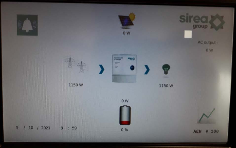
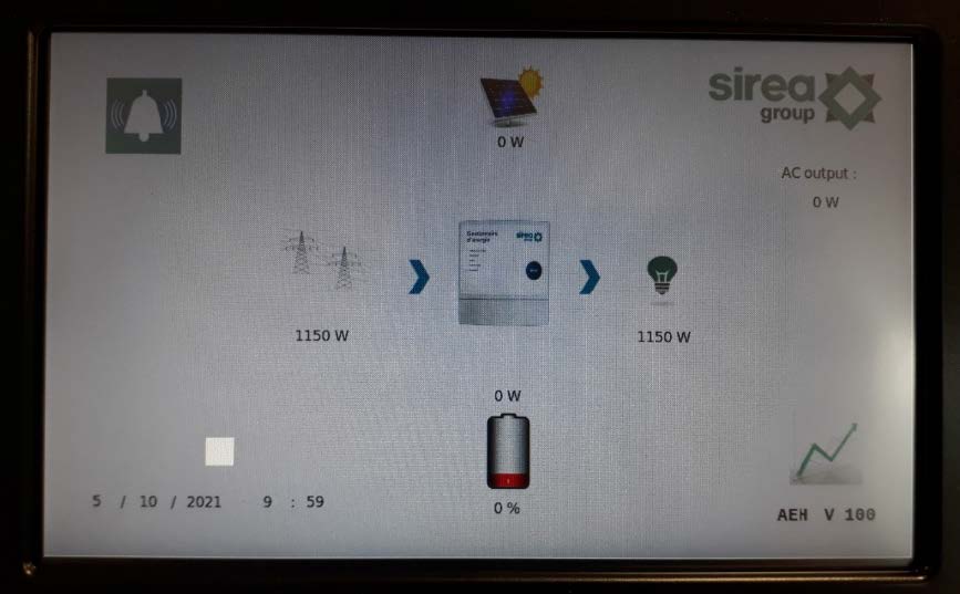
User can view the information of the cabinet operation on the LCD touch screen. After powering on the LCD will enter on the home page after about 15s. Then you can begin to read the information. At the first power on of the screen, you will have to configure the touch screen by touching the 4 square buttons one by one as shown below :
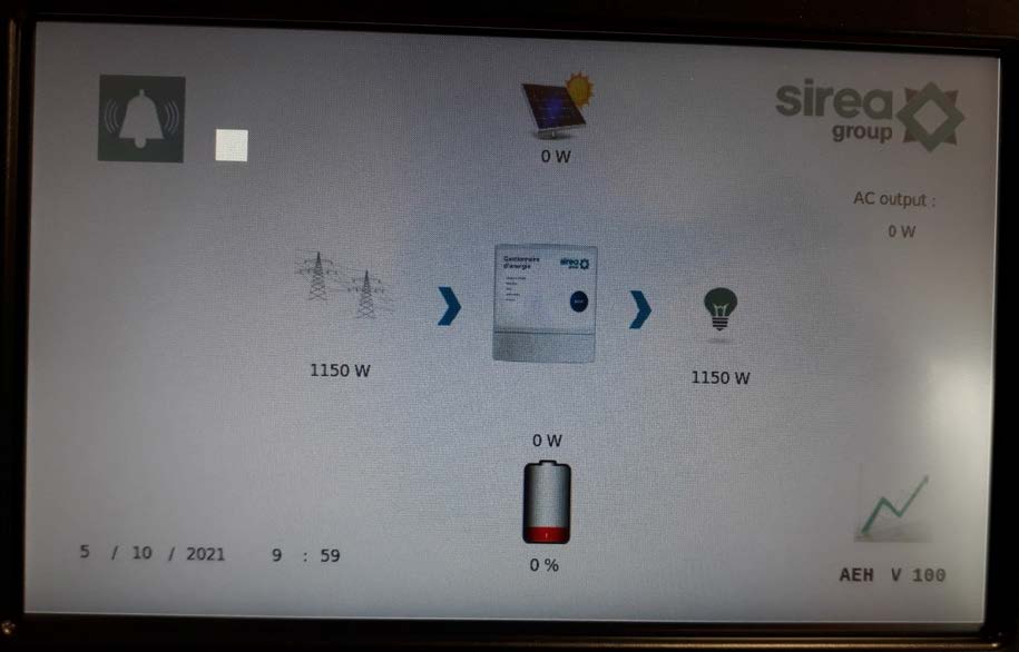
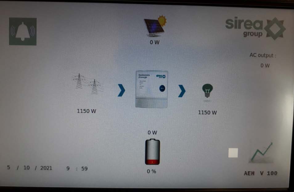
Then you will be able to read the main information of the cabinet.
Below, a description of an example of information which can appear on the system.
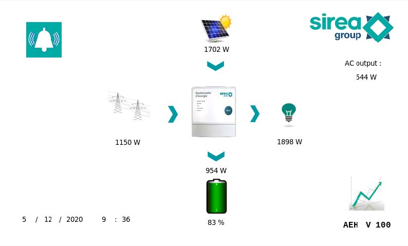
On this situation, the photovoltaic power is mixed with grid power to charge battery and ensure load power.
The total amount of load power is 1898W and a backup load power include in the total load is 544W. If there is a grid blackout, the battery will continue to power only the backup load of 544W in off grid mode.
On the battery side, the state of charge (SOC) is 83% and the battery is charging at 954 W.
5.2 History
You can select the graphical page to see historical data by clicking on the following
button on the main page
Note : You can always go back to the home page by clicking the home button on the bottom left corner
On the graphical view, you will be able to see historical data of the cabinet (grid, genset if present, photovoltaic and load consumption).
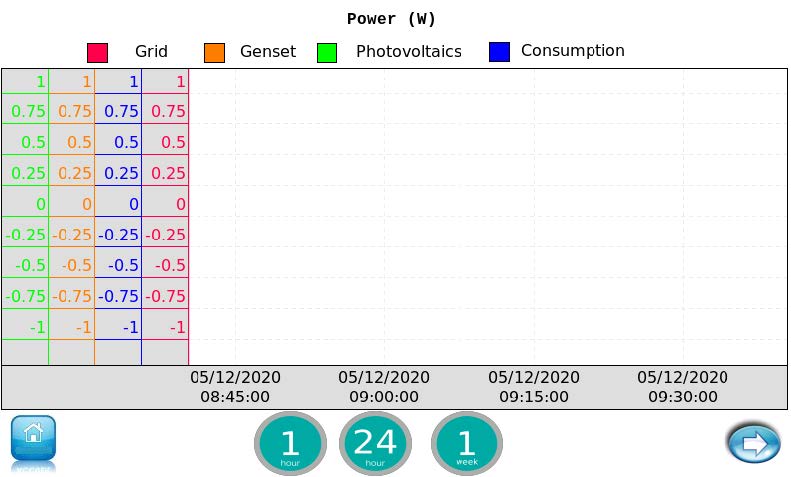
You can select the time range view (1 hour, 24 hours or 1 week), the default range is 1 hour.
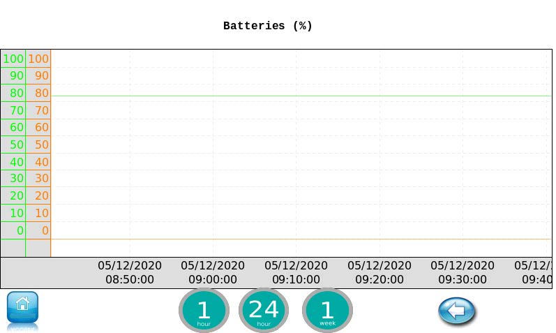
On the next page (button on the bottom right corner), you can see information related to the battery(ies). In green the state of charge SOC and orange the state of health SOH of the battery(ies).
5.3 Alarms
If an alarm is set, a buzzer is rising and a bell is shown on the top left corner of the home page. After clicking on it, you will be able to see the current alarms.
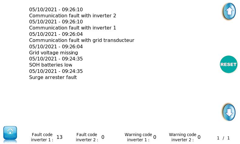
Here is the list of the cabinet alarms which can appear on this alarm page:
- Battery API low need replacement
- Clock update online fault
- Communication fault with grid transducteur
- Communication fault with AEH 1
- Communication fault with AEH 2
- Grid voltage missing
- Low battery voltage
- Onduleur 1 in fault (fault code)
- Onduleur 2 in fault (fault code)
- PV fault (24h without PV)
- SOH batteries low
- Surge arrester fault
Here is the list of the AEH’s fault code which can appears on the bottom of the alarm page:
| Fault code number | Fault code list |
|---|---|
| 1 | BUS exceed the upper limit |
| 2 | BUS drop to the lower limit |
| 3 | BUS soft start circuit timeout |
| 4 | AEH voltage soft start timeout |
| 5 | AEH current exceed the upper limit |
| 6 | Temperature over |
| 7 | AEH relay work abnormal |
| 8 | Current sample abnormal when AEH doesn’t work |
| 9 | Solar input voltage exceed upper limit |
| 10 | SPS power voltage abnormal |
| 11 | Solar input current exceed upper limit |
| 12 | Leakage current exceed permit range |
| 13 | Solar insulation resistance too low |
| 14 | AEH DC current exceed permit range when feed power |
| 15 | The AC input voltage or frequency has been detected different between master CPU and slave CPU |
| 16 | Leakage current detect circuit abnormal when AEH doesn’t work |
| 17 | Communication loss between master CPU and slave CPU |
| 18 | Communicate data discordant between master CPU and slave CPU |
| 19 | AC input ground wire loss |
| 22 | Battery voltage exceed upper limit |
| 23 | Overload |
| 24 | Battery disconnected |
| 26 | AC output short |
| 27 | Fan lock |
| 32 | Battery DC-DC current over |
| 33 | AC output voltage too low |
| 34 | AC output voltage too high |
| 35 | Control board wiring error |
| 36 | AC circuit voltage sample error |
| 37 | AC N wire current over |
| 60 | Negative power detected |
| 61 | Driver signal lost from relay board |
| 62 | Communication lost between main board and relay board |
| 63 | Versions are different between main board and relay board |
| 71 | Parallel version is incompatible |
| 72 | O/P current detection abnormal |
| 80 | CAN lost |
| 81 | HOST lost |
| 82 | SYN lost |
6. Routine maintenance
ln order to ensure the normal operation of the AEH, regular maintenance work is required. Recommended routine maintenance cycle and work, as shown in table below :
| Action | Frequency |
|---|---|
| Clean or replace the dust screen | Half a year |
| Check the dust, moisture or condensation inside the cabinet | Every month |
| Check the cable connections, and fix the screw if necessary | Every month |
| Check the warning label, add or replace some if necessary | Every month |
| Manual checks AC and DC circuit breakers | Every month |
| Check if there is an abnormal sound when the AEH is operating | Every week |
Danger
All maintenance operations must be carried out in the condition that the DC side and AC side of the AEH, PV module and AC distribution cabinet switch are all disconnected. Maintenance must be proceeded only after AC and DC are disconnected for at least 5 minutes, in order to avoid electric shock!
Waste disposal
The AEH will not cause environmental pollution, since all the components meet the requirements of environmental protection. According to environmental protection requirements, the user shall dispose of the AEH in accordance with the relevant laws and regulations.