Last update on
- 1. Introduction
- 2. Characteristics
- 3. Connections
- 4. Saved variables
- 5. Safety and warnings
- 6. Protection device
- 7. Elimination
- 8. Cleaning
- 9. Technical features
1. Introduction
This manual describes the specifics of the MicroARM-A1.
For information common to programming, see the “MicroLADDER manual”. To visualize better the corresponding addresses in MicroLADDER, they appear in color, on the sides of the diagrams. NC stands for not connected.
2. Characteristics
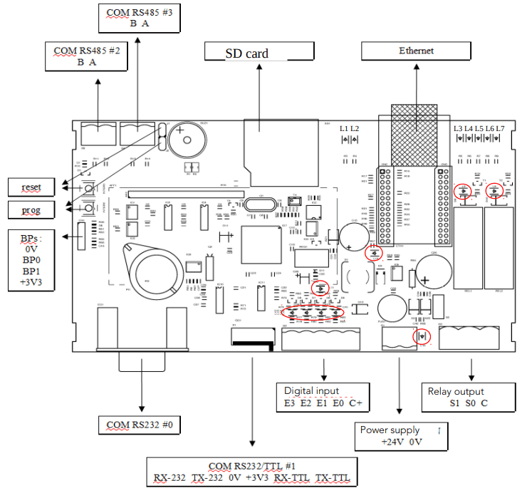
2.1 Board presentation
- ARM7 LPC2368 Porcessor
- 512 ko Flash (to save the monitor and the application) and 32 ko RAM
- 1 RS232 (COM 0) port with SubD 9 points connector for loading or free of use
- 1 RS232 TTL port or 12V (COM1) for loading or free of use
- 2 RS485 (COM2 and COM3) ports for loading or free of use
- 1 RTC (Real Time clock) on I2C bus with backup battery
- 1 EEPROM 16 Ko on I2C bus (for variables backup)
- 1 Ethernet module (optional) with 4 sockets
- 1 display 2×16 characters
- 1 buzzer
- 1 connector for the SD card (the card must be formated in FAT32)
- 4 digital input with a display LED
- 2 digital output in relay with a display LED
- 1 push-button switch reset (inter 3) (located next to the RS485 communication port picked up by the jumper J1
- 1 push-button switch to load programs (inter 2) (located next to the IHM connector) picked up by jumper J2
- 1 IHM connector allowing to use 2 push-button
2.2 LED significations
| L1 | Presence of a SD card |
| L2 | Working stat of the Programmable Logic Controller (PLC) |
| L3 to L7 | Ethernet Port |
| L8 and L9 | Digital output |
| L10 | Presence of a 5V tension |
| L11 | Presence of a 3.3V tension |
| L12 to L15 | Digital input |
| L16 | Presence of supply voltage |
See red circles on drawing in section 2.1
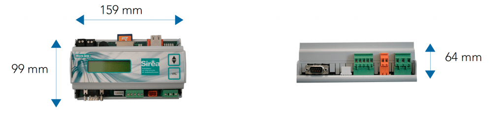
2.3 Dimensions
3. Connections
3.1 Digital

Digital input : value range from 0 to 1.

Digital output with relay : value range from 0 to 1.
3.2 Communication port
3.2.1 COM0 RS232
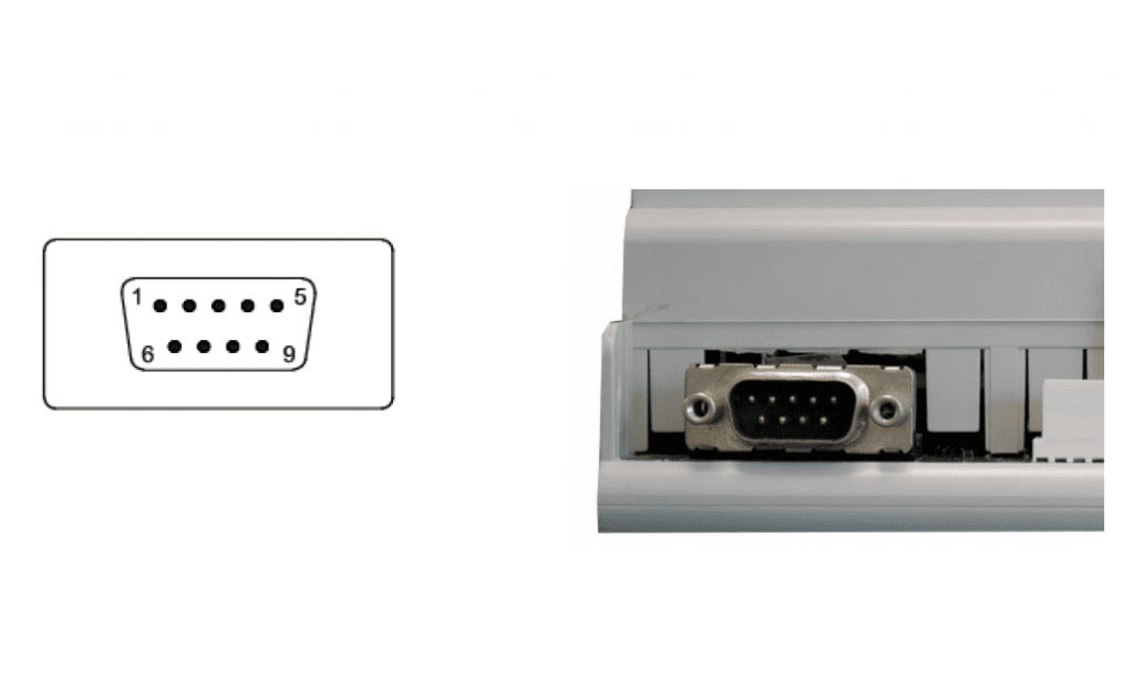
Standard broaching on DB9
- NC
- RX0
- TX0
- NC
- 0V
- NC
- NC
- NC
- NC
3.2.2 COM1 RS232 TTL or standard
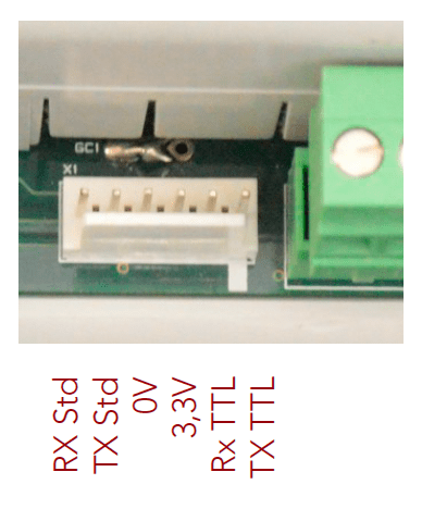
On the SAV1119B card, there is a double welding point shunt GC1 that allows to configurate the signal in TTL or 12V. This double welding point shunt does not exist on SAV1119A card.
The pins go from 6 to 1.
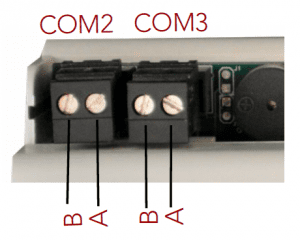
3.2.3 COM2 and COM3 RS485
3.3 HMI inputs and outputs (Human Machine Interface)

Value range from 0 to 1.
Backlight : %Q0
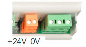
3.4 Power supply
4. Saved variables
There is no saved RAM and FRAM and there is no history management (events, alarms and traces)
The EEPROM address is KC_EEPROM_UC_ADR. The number of bytes reserved by the system at the beginning of EEPROM is 80 bytes. The size of the character buffer (VcEepromBuf []) is 128. The pages are 64 bytes. The size of the EEPROM is 16384 bytes = 16kb.
5. Safety and warnings
Warning
If the device is not used as per these instructions, the safety of people and equipment can be compromised. We disclaim any liability for any material damage or due to improper handling or failure to comply with the safety instructions.
The interventions on the devices must be made by staff who are competent to work on electric installations.
Before all interventions, all power supplies must be switched off. The cutting devices on the installation must be dimensioned and placed according to the standard UTE C
15-100.
For all interventions on a device installed on an electric installation, the Personal Protective Equipment (PPE) as defined by the safety regulations on the electric installations must be carried by the worker.
In the event of a failure or malfunction, the device must not be opened and must be
returned to the factory.
Observe the following pictograms:
 | Warning. On the product label this symbol means that the notice must be consulted. In this manual, this symbol indicates important information. |
 | Direct current. |
 | This device is CE approved and complies with the national and European guidelines. |
6. Protection device
Quick fuse protections must be positioned on the 24 volt continuous start feeding the PLC. These fuses will be sized according to the number of devices set in series behind the start.
7. Elimination

Old electronic devices are recyclables goods that should not be thrown into the trash can. If the device reaches the end of its life, it should be eliminated in accordance with the legal regulations in force to the recovery centres in your municipality. Elimination in the household trashes is prohibited.
8. Cleaning
For cleaning, use a clean, dry, antistatic, lint-free cloth without corrosive products.
9. Technical features
| Power supply | 18 to 28 V |
| Maximum operating Altitude | 2000m |
| Maximum operating Temperature | 45 °C |
| Maximum Operating Humidity | 70 % |