
Last update on
- 1. Introduction
- 2. Characterisitcs
- 3. Connections
- 4. Saved variables
- 5. Safety and warnings
- 6. Protection device
- 7. Elimination
- 8. Cleaning
- 9. Technical features
1. Introduction
This manual describes the specific features of the MicroARM-A8.
For information common to programming, see the “MicroLADDER manual”. To visualize better the corresponding addresses in MicroLADDER, they appear in color, on the sides of the diagrams.
2. Characterisitcs
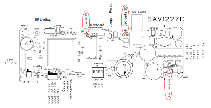
2.1 Board presentation
- ARM7 LPC1788 Cortex Processor
- 512Ko Flash (to save the monitor and the application)
- 16Mo of video RAM
- 512Ko of saved RAM
- 1 RS232 TTL (COM0) port for loading or free of use
- 1 RS485 (COM1) port for loading or free of use with the jumper termination resistance
- 1 internal RTC (Real Time clock) with backup battery
- 1 connector for graphic display 2,4 inches (320 x 240 pixels) with backlight
- 1 buzzer
- 1 microSD card holder (the card must be formated in FAT32)
- 4 configuration switches
- 1 connector for 5 keys keyboard
- 1 pressure and temperature sensor mounted on the board
- 1 jumper for the reset (J1) (located next to the keyboard connector)
- 1 push-button to change the program (inter 1) (located next to the buzzer)
2.2 LED significations
| L1 | Working state of the PLC (next to the keyboard connector) |
| L2 | Presence of a SD card (next to the microSD card) |
| L3 | Presence of tension supply (next to the supply connecotr /RS485) |
See red circles on drawing in chapter 2.1
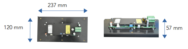
2.3 Dimensions
3. Connections
The following wiring diagrams are in the same direction as the layout diagrams of the card at the beginning of this document. The line symbolizes the edge of the board.
3.1 Communication port
3.1.1 COM0 RS232 TTL

| 1 | 2 | 3 | 4 |
| 3.3V | TX0 | RX0 | 0V |
3.1.2 COM1 RS485
See pinning on implantation.It is possible to plug from above and from below.
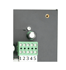
| 1 | 2 | 3 | 4 | 5 |
| Power supply+ | Power supply- | A | B | 0V |
| Power supply+ | Power supply- | A | B | 0V |
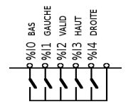
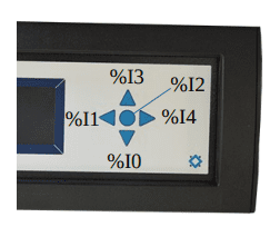
3.2 HMI inputs
Value range from 0 to 1. The description of the keys can vary following the lexan of the keyboard.
%Q0 : Off / On of the screen backlight
%Q1 : buzzer
%QW0 : screen backlight
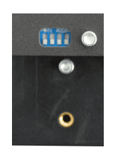
3.3 Power supply
Photo ARM 8
3.4 Diverses outputs
3.4.1 Pressure and temperature sensor
This sensor is located on the board
% IW100: temperature in tenth of a degree
% IW101: pressure in hectopascal
3.4.2 Configuration switches
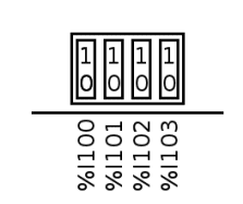
Value range from 0 to 1.
4. Saved variables
There’s a saved RAM. This allows to manage histories.
5. Safety and warnings
Warning
If the device is not used as per these instructions, the safety of people and equipment can be compromised. We disclaim any liability for any material damage or due to improper handling or failure to comply with the safety instructions.
The interventions on the devices must be made by staff who are competent to work on electric installations.
Before all interventions, all power supplies must be switched off. The cutting devices on the installation must be dimensioned and placed according to the standard UTE C
15-100.
For all interventions on a device installed on an electric installation, the Personal Protective Equipment (PPE) as defined by the safety regulations on the electric installations must be carried by the worker.
In the event of a failure or malfunction, the device must not be opened and must be
returned to the factory.
Observe the following pictograms :
 | Warning. On the product label this symbol means that the notice must be consulted. In this manual, this symbol indicates important information. |
 | Direct current. |
 | This device is CE approved and complies with the national and European guidelines. |
6. Protection device
Quick fuse protections must be positioned on the 24 volt continuous start feeding the PLC. These fuses will be sized according to the number of devices set in series behind the start.
7. Elimination

Old electronic devices are recyclables goods that should not be thrown into the trash can. If the device reaches the end of its life, it should be eliminated in accordance with the legal regulations in force to the recovery centres in your municipality. Elimination in the household trashes is prohibited.
8. Cleaning
For cleaning, use a clean, dry, antistatic, lint-free cloth without corrosive products.
9. Technical features
| Power supply | 10 to 28 V |
| Maximum operating altitude | 2000 m |
| Maximum operating temperature | 45°C |
| Maximum operating humidity | 70 % |