Last update on
- 1. Introduction
- 2. Characteristics
- 3. Connections
- 4. Saved variables
- 5. Safety and warnings
- 6. Protection device
- 7. Elimination
- 8. Cleaning
- 9. Technical features
1. Introduction
This manual describes the specifics of the MicroARM7-A2.
For information common to programming, see the “MicroLADDER manual”. To visualize better the corresponding addresses in MicroLADDER, they appear in color, on the sides of the diagrams.
2. Characteristics
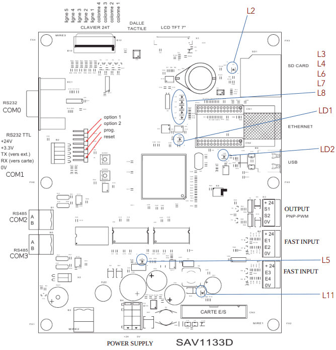
2.1 UC Board presentation
- ARM7 LPC2478 Processor
- 512Ko Flash (to save the monitor and the application)
- 16Mo of saved video RAM
- 512Ko of saved RAM (for variable backup)
- 1 RS232 (COM 0) port with SubD9 points connector for loading or free of use
- 1 RS232 TTL (COM1) port for loading or free of use
- 2 ports RS485 (COM2 et COM3) pour chargement ou libre d’utilisation
- 1 Ethernet connector with 4 autonomous communication sockets (optional)
- 1 USB Host port
- 1 RTC (Real Time clock) on I2C bus with backup battery
- 1 EEPROM 16 Ko I2C bus
- 1 connector for 7 inches touch-screen graphic display (800 x 480 pixels) or 4.3 inches touch-screen graphic display (480 x 272 pixels)
- 1 buzzer
- 1 SD card connector (the card must be formated in FAT32)
- 4 digital inputs
- 2 digital output PWM with transistor
- 1 reset push-button (inter 2) picked up by jumper J2
- 1 push-button to change the program (inter 1) picked up by jumper J1
- 1 keyboard connector (4 columns – 6 lines)
2.2 LED significations
| LD1 | State order of the PLC |
| L2 | Presence of a SD card |
| L3, L4, L6, L7 and L8 | Ethernet |
| L5 | Presence of tension supply |
| L11 | Presence of a 5 volts tension |
| LD2 | USB |
See blue circles on drawing in section 2.1
2.3 IO board presentation
- 16 digital inputs
- 1EEPROM 16 Ko on I2C bus (to save variables)
- 16 relay digital outputs (250V – 10A)
- 8 analog inputs 0-10V, 0-20mA or PT100 (configuration for each jumper) (12 bits)
- 2 analog outputs 0-10V (12 bits)
2.4 LED significations
| L1 | Presence of a 12 volts tension |
| L5 | Presence of a 5 volts tension |
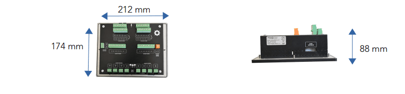
2.5 Dimensions
3. Connections
3.1 Digital
3.1.1 Digital Input
| 1 | 2 | 3 | 4 | 5 | 6 | 7 | 8 |
| %I123 | %I122 | %I121 | %I120 | %I119 | %I118 | %I117 | %I116 |

| 9 | 10 | 11 | 12 | 13 | 14 | 15 | 16 |
| %I115 | %I114 | %I113 | %I112 | %I111 | %I110 | %I109 | %I108 |
3.1.2 Fast digital input
| 1 | 2 | 3 | 4 |
| %I103 | %I102 | %I101 | %I100 |
3.1.2 Digital output
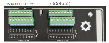
| 1 | 2 | 3 | 4 | 5 | 6 | 7 | 8 |
| %Q107 | %Q106 | %Q105 | %Q104 | %Q103 | %Q102 | %Q101 | %Q100 |
| 9 | 10 | 11 | 12 | 13 | 14 | 15 | 16 |
| %Q115 | %Q114 | %Q113 | %Q112 | %Q111 | %Q110 | %Q109 | %Q108 |
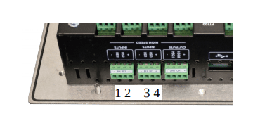
3.1.3 Fast digital output
%QW102 (1) to %QW103 (2) : PWM output
3.2 Analog
3.2.1 Analog input
From %IW100 to %IW107 : analog input 0-20mA, 0-10V or PT100. Until the end of 2013, the measuring range of the analog inputs configured in PT100 was -50/150 °c.From January 2014, the game of resistance of the cards and the system code have been modified to have a range of 0/350 °C.
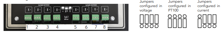
| 1 | 2 | 3 | 4 | 5 | 6 | 7 | 8 |
| IW7 | IW6 | IW5 | IW4 | IW3 | IW2 | IW1 | IW0 |
| %IW107 | %IW106 | %IW105 | %IW104 | %IW103 | %IW102 | %IW101 | %IW100 |
3.2.2 Analog output
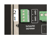
%QW100 (1) %QW101 (2) : analogic output 0-10V
3.3 Communication port
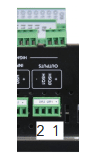
3.3.1 COM0 RS232
Standard broaching on DB9
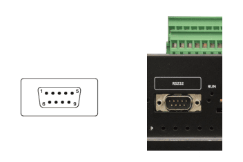
| 1 | NC | 6 | NC |
| 2 | RX0 | 7 | NC |
| 3 | TX0 | 8 | NC |
| 4 | NC | 9 | NC |
| 5 | 0V |
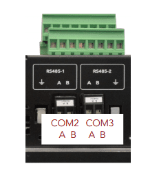
3.3.2 COM2 and COM3 RS485
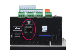
3.3.3 Ethernet port
3.4 Human Machine Interface (HMI)
%IW0 : horizontal position of the clicked point on the screen and %IW1 : vertical position of the clicked point on the screen
%Q0 : activation of the backlight
%Q1 : buzzer
%QW0 : power of the backlight
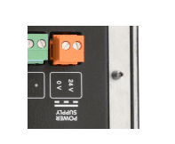
3.5 Power supply
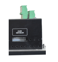
3.6 Keyboard
From %IO to %I24
4. Saved variables
There’s a saved RAM. This allows to manage histories.
4.1 Memory reservation in video RAM
Return = GfxCreateArray (Parameter1, Parameter2)
This function allows to reserve memory in video RAM.
Return: pointer type variable (unsigned char *). To reserve memory for another type of variable, you have to cast.
Parameter1: Byte length for 1 element.
Parameter2: The number of items to reserve.
Example:
Text Char [20];
5. Safety and warnings
Warning
If the device is not used as per these instructions, the safety of people and equipment can be compromised. We disclaim any liability for any material damage or due to improper handling or failure to comply with the safety instructions.
The interventions on the devices must be made by staff who are competent to work on electric installations.
Before all interventions, all power supplies must be switched off. The cutting devices on the installation must be dimensioned and placed according to the standard UTE C
15-100.
For all interventions on a device installed on an electric installation, the Personal Protective Equipment (PPE) as defined by the safety regulations on the electric installations must be carried by the worker.
In the event of a failure or malfunction, the device must not be opened and must be
returned to the factory.
Observe the following pictograms:
 | Warning. On the product label this symbol means that the notice must be consulted. In this manual, this symbol indicates important information. |
 | Direct current. |
 | This device is CE approved and complies with the national and European guidelines. |
6. Protection device
Quick fuse protections must be positioned on the 24 volt continuous start feeding the PLC. These fuses will be sized according to the number of devices set in series behind the start.
7. Elimination

Old electronic devices are recyclables goods that should not be thrown into the trash can. If the device reaches the end of its life, it should be eliminated in accordance with the legal regulations in force to the recovery centres in your municipality. Elimination in the household trashes is prohibited.
8. Cleaning
For cleaning, use a clean, dry, antistatic, lint-free cloth without corrosive products.
9. Technical features
| Power supply | 18 to 28 V |
| Maximum operating Altitude | 2000m |
| Maximum operating Temperature | 45 °C |
| Maximum Operating Humidity | 70 % |