Last update on
- 1. Introduction
- 2. Characteristics
- 3. Connections
- 4. Loading an application
- 5. Safety and warnings
- 6. Protection device
- 7. Elimination
- 8. Cleaning
- 9. Technical features
1. Introduction
This manual describes the specifics of the MicroARM-A4.
For information common to programming, see the “MicroLADDER manual”. To visualize better the corresponding addresses in MicroLADDER, they appear in color, on the sides of the diagrams.
Do not declare the digital output if the analog outputs are to be used.
2. Characteristics
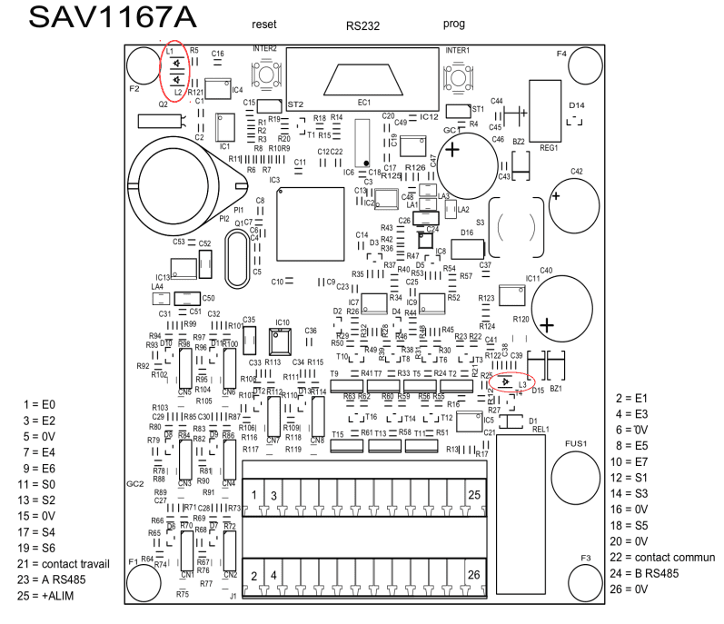
2.1 Board presentation
- ARM7 LPC2368 Processor
- 512Ko Flash (to save the monitor and the application) and 32Ko RAM
- 2 RS232 (COM0 and COM2) ports on the same SubD9 points connecto for loading or free use
- 1 RS485 port (COM1) for loading or free of use
- 1 RTC (Real Time clock) on bus I2C with backup battery (optional)
- 1 EEPROM 16 Ko on bus I2C (to backup variables)
- 1 SRAM 32Ko on bus I2C (to backup variables) (optional)
- 8 inputs can be used as digital or analog (0-10V)
- 4 outputs with transistor can be used as digital or analog (0-10V)
- 3 digital outputs with transistor
- 1 digital output with relay
- 1 reset push-button (inter 2) (located at the left of RS232 connector, jumper side)
- 1 push-button to change the program (inter 1) (located on the right of RS232 connector, relay side)
2.2 LED significations
| L1 | Working state of the PLC |
| L2 | Presence of a 3.3 volts tension |
| L3 | Presence of tension supply |
See red circles on drawing 2.1
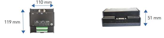
2.3 Dimensions
3. Connections
3.1 Digital
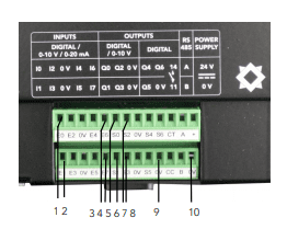
3.1.1 Digital Input
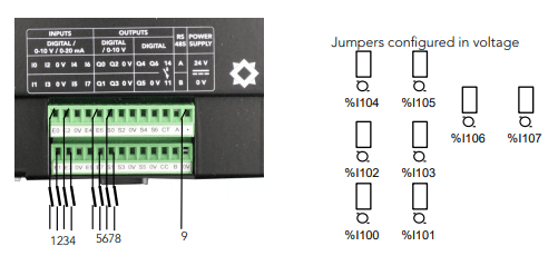
Value range from 0 to 1
| 1 | 2 | 3 | 4 | 5 | 6 | 7 | 8 | 9 |
| %I100 | %I101 | %I102 | %I103 | %I104 | %I105 | %I106 | %I107 | +Alim |
3.1.2 Digital output with PNP transistor
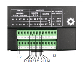
Value range from 0 to 1.
| 1 | 2 | 3 | 4 | 5 | 6 | 7 |
| Commun 0V | Commun 0V | %Q100 | %Q101 | %Q102 | %Q103 | Commun 0V |
| 8 | 9 | 10 | 11 | 12 | 13 |
| Commun 0V | %Q104 | %Q105 | %Q106 | Commun 0V | Commun 0V |
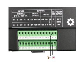
3.1.3 Digital output with relay
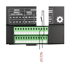
Value range from 0 to 1.
3.2 Analog
3.2.1 Analog input
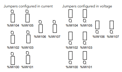
Value range from 0 to 10000 if configured in voltage and 0 to 20000 if configured in current
| 1 | 2 | 3 | 4 | 5 | 6 |
| %IW100 | %IW101 | %IW102 | %IW103 | Commun 0V | Commun 0V |
| 7 | 8 | 9 | 10 | 11 |
| %IW104 | %IW105 | %IW106 | %IW107 | Commun 0V |
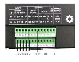
3.2.2 Analog output
Value range from 0 to 10000. Do not declare the digital output if the analog output must be used.
| 1 | 2 | 3 | 4 | 5 |
| Commun 0V | Commun 0V | %QW100 | %QW101 | %QW102 |
| 6 | 7 | 8 | 9 | 10 |
| %QW103 | Commun 0V | Commun 0V | Commun 0V | Commun 0V |
3.3 Communication port
3.3.1 COM0 RS232 and COM2 RS232
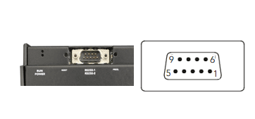
Standard pin on DB9.
Pins on 7 and 8 are used for the COM2.
This communication port is located on DB9 connector.
| 1 | NC | 6 | NC |
| 2 | RX0 | 7 | TX2 |
| 3 | TX0 | 8 | RX2 |
| 4 | NC | 9 | NC |
| 5 | GND 0V |
3.3.2 COM1 RS485
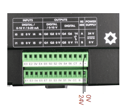
3.4 Power supply
4. Loading an application
Since there is no SD card, the loading must be done by MicroControl.
Before the first load, on power-up, the PLC attempts to launch the application that does not exist (default settings) and crashes.
To avoid blocking, press the PROG button in the first second after the power-on. This
forces the PLC to stay on the monitor. It is then possible to act with MicroControl.
5. Safety and warnings
Warning
If the device is not used as per these instructions, the safety of people and equipment can be compromised. We disclaim any liability for any material damage or due to improper handling or failure to comply with the safety instructions.
The interventions on the devices must be made by staff who are competent to work on electric installations.
Before all interventions, all power supplies must be switched off. The cutting devices on the installation must be dimensioned and placed according to the standard UTE C
15-100.
For all interventions on a device installed on an electric installation, the Personal Protective Equipment (PPE) as defined by the safety regulations on the electric installations must be carried by the worker.
In the event of a failure or malfunction, the device must not be opened and must be
returned to the factory.
Observe the following pictograms :
 | Warning. On the product label this symbol means that the notice must be consulted. In this manual, this symbol indicates important information. |
 | Direct current. |
 | This device is CE approved and complies with the national and European guidelines. |
6. Protection device
Quick fuse protections must be positioned on the 24 volt continuous start feeding the PLC. These fuses will be sized according to the number of devices set in series behind the start.
7. Elimination

Old electronic devices are recyclables goods that should not be thrown into the trash can. If the device reaches the end of its life, it should be eliminated in accordance with the legal regulations in force to the recovery centres in your municipality. Elimination in the household trashes is prohibited.
8. Cleaning
For cleaning, use a clean, dry, antistatic, lint-free cloth without corrosive products.
9. Technical features
| Power supply | 10 to 28 V |
| Maximum operating altitude | 2000 m |
| Maximum operating temperature | 45 °C |
| Maximum operating humidity | 70 % |