Last update on
- 1. Introduction
- 2. Product presentation
- 2.1 Concerned references
- 2.2 Dimensions
- 2.3 Description of front controls
- 2.4 List of possible errors
- 2.5 Safety measures and warnings
- 2.6 CEM inverter and noise level
- 2.7 Security features
- 2.8 Elimination
- 2.9 Cleaning
- 2.10 Product identification
- 2.11 Operating principle
- 2.12 Operating functions
- 2.13 Electrical diagrams
- 2.14 Protection
- 2.15 Storage
- 3. Commissioning of the cabinet
- 4. Option configuration
- 5. Implementation
1. Introduction
1.1 Targeted reader
Only professional electricians or qualified personnel can carry and install this device.
The operator must be fully acquainted with the structure and the operating principle of the energy storage system.
The operator must be fully acquainted with these operating instructions.
The operator must be fully acquainted with the local regulations of the project.
1.2 How to use this document
Read this manual before installing the AEA cabinet.
Keep this manual within reach at all times.
The content of this manual will be periodically updated or revised if necessary. However, deviations can not be excluded.
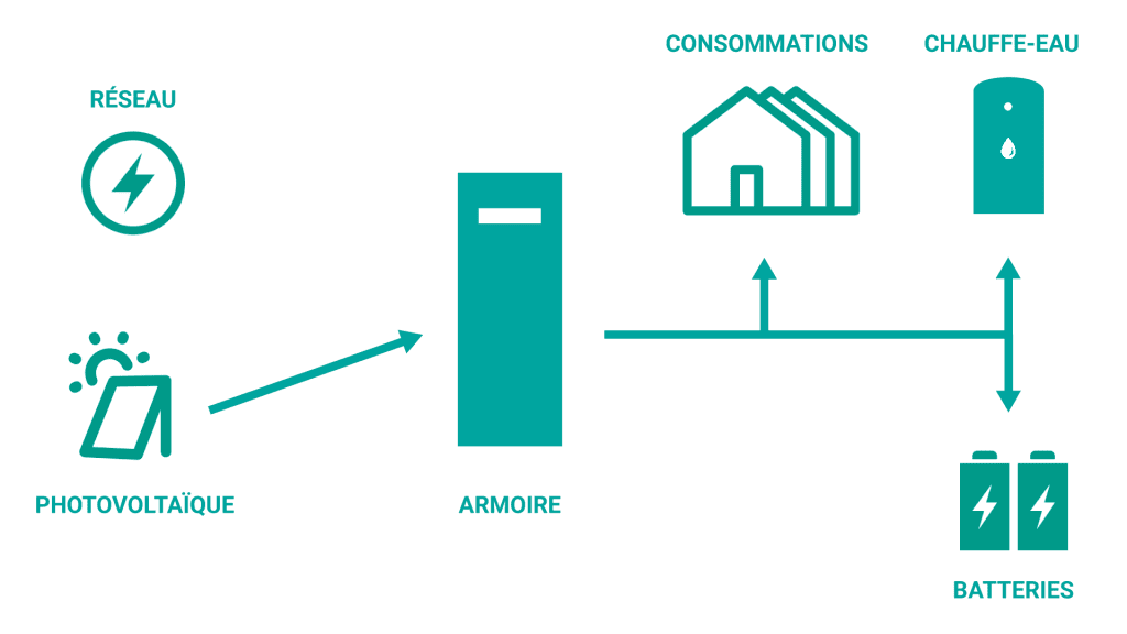
2. Product presentation
The AEA cabinet has been developed in order to provide a reliable power supply from conventional and renewable energy sources.
This cabinet promotes self-production and facilitates self-consommation of generated electrical energy, to reduce electricity consumption coming from the grid.
The AEA cabinet offers the possibility to monitor and optimize a single-phase consumption place and control a resistive hot water tank (option).
2.1 Concerned references
| Reference | Product name |
|---|---|
| 2EN01-00310 | AEA3000-S on-grid (ex: AEA 3000 Slim) |
| 2EN01-00318 | AEA3000-S off-grid |
| 2EN01-00317 | AEA3000-M on-grid (ex: AEA 3000+) |
| 2EN01-01400 | AEA3000-M off-grid |
| 2EN01-00312 | AEA3000-L on-grid |
| 2EN01-01500 | AEA3000-L off-grid |
| 2EN01-00309 | AEA5000-S on-grid (ex: AEA 5000 Slim) |
| 2EN01-01600 | AEA5000-S off-grid |
| 2EN01-00311 | AEA5000-M on-grid |
| 2EN01-00212 | AEA5000-M off-grid (ex: AEA 5000 off-grid) |
| )2EN01-00319 | AEA5000-L on-grid |
| 2EN01-01700 | AEA5000-L off-grid |
| 2EN01-00314 | AEA10000-L on-grid |
| 2EN01-00305 | AEA10000-L off-grid |
| 2EN01-00306 | AEA10000-L-3PH on-grid |
| 2EN01-00320 | AEA10000-L-3PH off-grid |
2.2 Dimensions
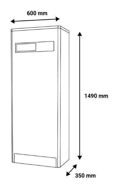 | 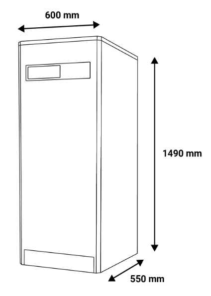 | 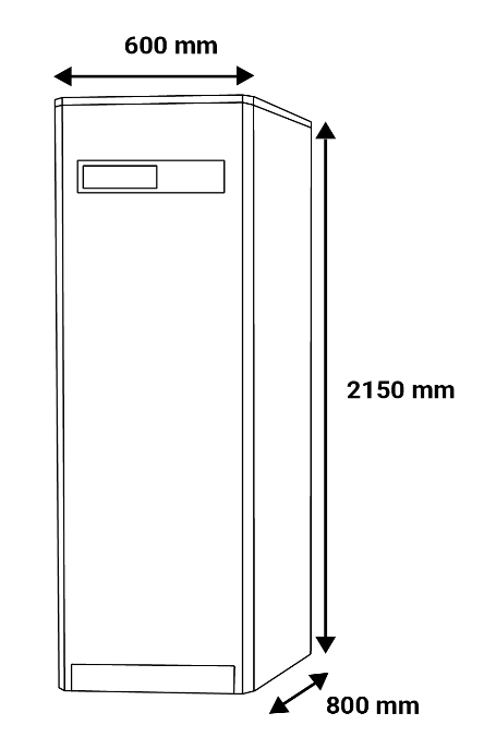 |
| AEA size S 60 x 149 x 35 cm | AEA size M 60 x 149 x 55 cm | AEA size L 60 x 215 x 80 cm |
Warning
Do not put anything on top.
Leave a minimum space of 5 cm on each side and behind the cabinet, and 20 cm above the cabinet.
2.3 Description of front controls
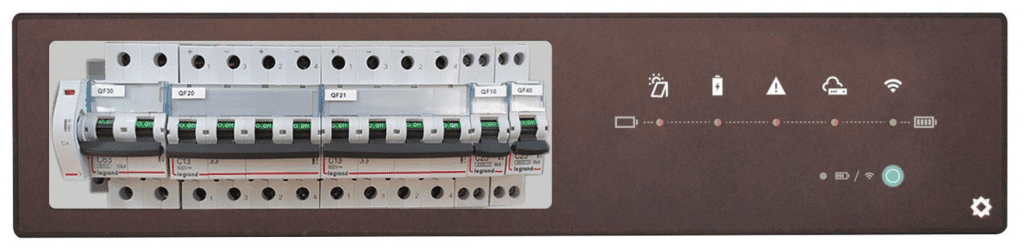
| Icon | Comments |
|---|---|
 | Solar indicator light 🟢 Static green : ongoing production but less production than consumption 🟢 Slow flashing green : ongoing production, the production covers the need of the housing, the excess is stored in the batterie 🟢 Fast flashing green : ongoing production, the production covers the need of the housing, the excess is stored in the batterie and the remaining excess is exported to the grid 🔴 Flashing red : back-up mode (optional) 🔴 Static red : Cabinet is off or no mode has been selected ⚫ Off : no production |
 | Battery indicator light 🟢 Flashing green : ongoing charge 🟢 Static green : ongoing discharge 🔴 Static red : low battery or other battery default ⚫ Off : no charge or discharge |
 | Error indicator light 🔴 Static red : at least one error ⚫ Off : no errors |
 | Teleprocessing indicator light 🟢 Static green : ongoing communication with the server 🔴 Static red : connxion error with the serve ⚫ Off : no IP address received (no DHCP connexion) |
 | Wifi indicator light 🟢 Static green : WiFi Network detected ⚫ Off : no WiFi Network detected |
| Mode Indicator light 🟢 Static green : Ongoing batterie’s SOC (level) displayed (temporary display if the button is pressed) ⚫ Off : Ongoing classic display |
2.4 List of possible errors
| Name | Action |
|---|---|
| Arrester error | Check the arresters shape FP10 / FP20 |
| Communication error RS485 with the inverter | Check the connections between the inverter and the controller (OND1 / API1) |
| Communication error RS485 with the BMS A16 | Check the connections between the controllers (API1 / API2) |
| Generator start signal error | Check the shape of the AC QF10 circuit breaker, the power generator and the connections |
| PV error (24h without production) | Check the shape of the PV QF20 circuit breaker |
| Communication error RS485 with the dimmer | Check the connections between the controllers (API1 / GDT1) |
| CAN communication error between BMS A16 and battery | Check the connections between the controller and battery (API2 / BAT) |
| CAN communication error between BMS A16 and inverter | Check the connections between the controller and inverter (API2 / OND1) |
| Missing EMS battery error | Restart the batteries by switching off QF30 |
| NumberOfSlaveProblem battery error | Restart the batteries by switching off QF30 |
| PowerBusInformation battery error | Restart the batteries by switching off QF30 |
| Low battery voltage | Restart the batteries by switching off QF30 |
| High battery voltage | Restart the batteries by switching off QF30 |
| GlobalIBMSAlarmState battery error | Restart the batteries by switching off QF30 |
| Battery IBMS configuration problem error | Restart the batteries by switching off QF30 |
| FaultList inverter error | Restart by switching off all circuit breakers, wait 1 min then relaunch |
| Inverter Alarm Information error | Restart by switching off all circuit breakers, wait 1 min then relaunch |
| Internal Information inverter error | Restart by switching off all circuit breakers, wait 1 min then relaunch |
| Battery Fault Information inverter error | Restart by switching off all circuit breakers, wait 1 min then relaunch |
| PackFaultSN inverter error | Restart by switching off all circuit breakers, wait 1 min then relaunch |
| Error BMS wFaultAutomateSyst | Restart the batteries by switching off QF30 |
| Error BMS wFaultBmsSyst | Restart the batteries by switching off QF30 |
| Error BMS Fault0_7 | Restart the batteries by switching off QF30 |
| Error BMS Fault8_15 | Restart the batteries by switching off QF30 |
| Error BMS Fault16_23 | Restart the batteries by switching off QF30 |
| Error BMS Fault24_31 | Restart the batteries by switching off QF30 |
| Error BMS Fault32_35 | Restart the batteries by switching off QF30 |
| Low battery temperature | Check the room temperature |
| Low battery | Alert |
| Low battery state of health (SOH) | Alert |
| High battery temperature | Check the room temperature |
| High temperature of the dimmer NTC heat sink | Check the room temperature and the shape of the aeration grids |
| High temperature of the dimmer internal NTC | Check the room temperature and the shape of the aeration grids |
| WIFI detection error | Check the connections |
2.5 Safety measures and warnings
Warning
All damage due to non-compliance with the present operating instructions will result in the termination of the warranty ! We disclaim any liability for possible material or physical damages due to inappropriate handling or non-compliance with the safety directives.
In terms of safety, this equipment left the factory in perfect shape. In order to maintain this equipment in good shape and to ensure correct usage without risks, the user must consider the safety directives and Cautions of these operating instructions. For industrial installations, please note that accident prevention regulations about installation and electric material must be followed.
The installation of this kind of equipment must always be carried out by a qualified professional.
Opening caps or dismantling pieces might expose live elements ; before intervening on the equipment, it is necessary to unplug every voltage source. However, equipment’s capacitors can still be charged even when the AEA cabinet is disconnected. The AEA cabinet must be installed in a room at ambient temperature. If the proper functioning of the equipment can not be insured, it should be turned off and all accidental restarts shall be prevented. The installator should be contacted.
The AEA rating is IP32, the cabinet is made to be installed indoors.
Note the following pictograms :
 | Warning. On the product label this symbol means that the notice must be consulted. In this manual, this symbol indicates important information. |
 | Direct current. |
 | This device is CE approved and complies with the national and European guidelines. |
| | |
| Attention | Courant direct | Marquage CE |
| Sur l’étiquette du produit, ce symbole signifie que l’avis doit être consulté. Dans ce manuel, ce symbole indique des informations importantes. | A venir | Ce dispositif est homologué CE et est conforme aux lignes directrices nationales et européennes |
2.6 CEM inverter and noise level
Electromagnetic compatibility (EMC) is the requirement for electric equipment to properly work in an electromagnetic environment without causing itself unacceptable impact on that environment.
- Anti-interference porperty of the internal components
- Anti-interference property from the outside
- Impact of electromagnetic emissions on the environment
The inverter can generate noise and electromagnetic radiation while functionning. According to the EMC emissions and noise level, the AEA must be used in industrial environments. Therefore, staff should not stay near the cabinet for too long.
2.7 Security features
A safety system against short circuits must be placed on the 24 Volts continuous start supplying the controller. Those fuse will be sized depending on the amount of device connected in series after the start.
2.8 Elimination
Old electronic devices are recyclables goods that should not be thrown into the trash can. If the device reaches the end of its life, it should be eliminated in accordance with the legal regulations in force to the recovery centres in your municipality. Elimination in the household trashes is prohibited.
2.9 Cleaning
For cleaning, use a clean, dry, antistatic, lint-free cloth without corrosive products.
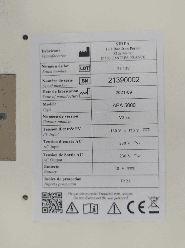
2.10 Product identification
To identify the AEA, a label with barcode is glued to the inner surface of the cabinet door. The serial number (SN) is given in the third line of the table.

2.11 Operating principle
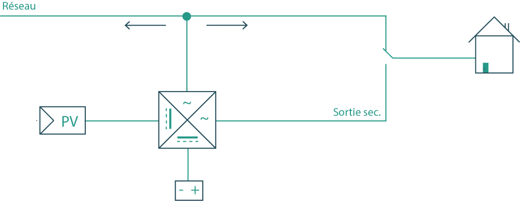
Energy originating from a renewable source is prioritarly used for consumption. In case of an excess of production, the energy is stocked in the battery. If the battery is fully charged, the solar panel output power will be restrained to prevent from injecting power into the grid. (In case of selling power to the grid, see paragraph 2.4).
When renewable energy production is not enough, the remaining energy needed for consumption will be supplied by the battery. If the battery is empty, the energy will be supplied by the grid.
When the need is superior to the cabinet maximum power output, the complement will be provided by the grid.
2.12 Operating functions
Grid frequency : 45Hz-55Hz
Grid voltage : 150V-283V
Depending on the installation, the AEA can be Ogg-Grid or On-Grid.
2.12.1 On-Grid functionning mode :
Batteries SOC above 21 %
- The AEA supplies power to regulate the power extracted from the grid to 0W.
- If there is more photovoltaic production than consumption, the production supplies both consumption and battery charge.
- If there is less production than consumption, the porduction combined with the batteries supplies the cunsumption.
- If the production combined with the batteries is not enough to cover the consumption, the grid supplies the rest.
Batteries SOC inferior or equal to 21 %
- Consumption is supplied by the grid solar power
- If there is more production than consumption, the production will charge the batteries.
- SOC will need to be at least 25% to restart regulation.
2.12.2 Off-Grid functionning mode
Batteries SOC above 21 %
- If there is more photovoltaic production than consumption, the production supplies both consumption and battery charge.
- If there is less production than consumption, combined with batteries, the production will supply consumption. There can not be more consumption than the rated power of the cabinet.
- When the SOC reaches 22%, the contact between the terminals XC1 and XC2 is closed (the power generator starts), the contact is closed until the batteries SOC is at least 60% (adjustable in the factory).
Batteries SOC inferior or equal to 21 %
- The inverter stops producing the 230V voltage (power cut). Batteries will need to have a SOC of at least 25% to restart the inverter.
2.13 Electrical diagrams
The AEA’s inverter converts direct current generated by the solar panels to DC on the bus, then either into DC to charge the battery or in AC. It also can convert DC coming from the battery into AC. Then AC is filtered into a sinusoidal electricity and injected in the grid via a medium voltage isolation transformer.
2.13.1 Standard electrical diagram
A venir
2.13.2 AEA 10000, 3 phased, electrical diagram

2.14 Protection
1.14.1 Anti-Islanding
When the local electricity grid is cut due to dysfunction or maintenance, the AEA will be physically separated from the grid, in order to protect the personnel working on the grid. The cabinet is thus compliant with applicable standards.
1.14.2 Lightning protection
The cabinet lightning protection is provided with a protection against overvoltage on the DC/AC side to prevent damaging the AEA.
2.15 Storage
If the installation or usage of the cabinet is done a long time after receiving it, it needs to be properly stored.
- Packaging must be put back on in his sending state
- The AEA can be stored only when it is shut down and completely closed
- In a dry room to protect the internal wiring from dust and humidity
- Storage temperature : Pylontech -20°C~60 °C SNAM 5°C~36°C
- Storage humidity : 0 %~90%
- Max. altitude : 2000 m
Warning
Storage is strictly prohibited wihtout packaging ! Avoid storage in direct sunlight. Keep the cabinet vertical and avoid putting things on top.
3. Commissioning of the cabinet
3.1 Battery installation
The AEA cabinet is made to receive batteries of the Phenix Batteries brand. To obtain complementary information on the batteries, refer to the accompanying manual. Batteries are delivered with their power cables. The power cable to be connected to the battery is already connected to the cabinet.
3.2 Battery implementation
Danger
Before dismounting the door, be sure that all power sources are switched off thanks to the circuit breakers.
3.2.1 Dismounting the front door


3.2.2 Setting up multiple batteries
- Push the battery along the guide rails until the end in order to leave enough space for the next battery. When you are in front of the cabinet, the DB9 communication plug should be on your left.
- Push the second battery along the guide rails, and still with the DB9 plug on your left.
3.2.3 Batteries connections for AEA3000 and 5000
Connect black connectors with black terminals and orange connectors with orange terminals.
3.2.4 Batteries connection for AEA 10 000
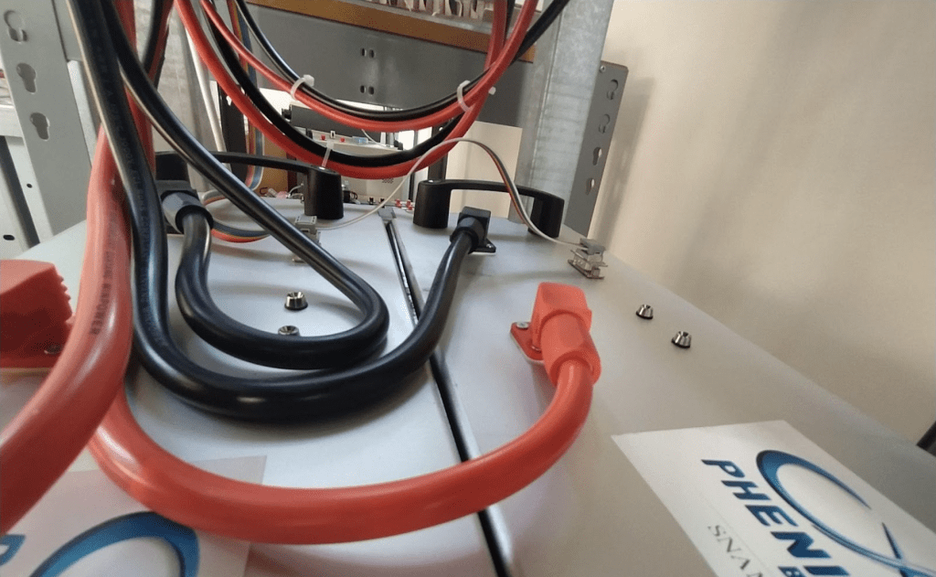
The AEA 10000 already has a BMS master integrated inside the cabinet. Once batteries are set up, Cables need to be connected as shown in the pictures. Power cables are represented in red.
Information
The MBMS must have its black terminal connected to the first battery of the chain.
The MBMS' red terminal must be connected to the last battery in the chain.
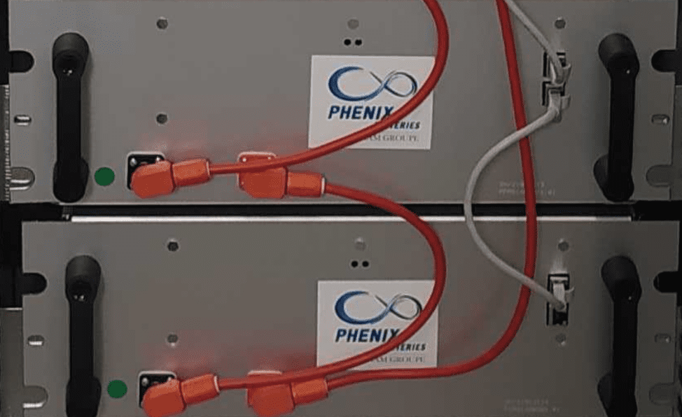
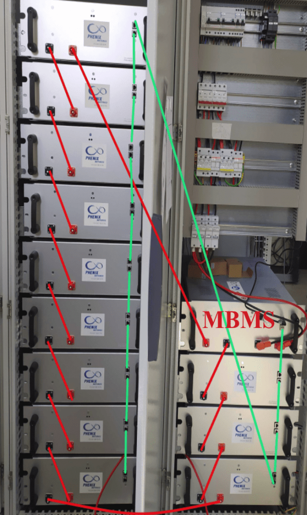
MBMS connection :
- Connect the MBMS’ black terminal to the black terminal of the battery below.
- Connect the MBMS’ red terminal to the red terminal of the last battery (the one one top of the left side in the picture).
- Connect the communication cables (green) as shown in the picture.
Danger
If you have an Off-Grid installation, as soon as the power cables are connected to the BMS the QF30 circuit breaker  has a voltage over 230V at its terminals (the orange sleeves notify that there is voltage even when the installation is powered down).
Check the DC voltage at the QF30 circuit breaker’s terminals.
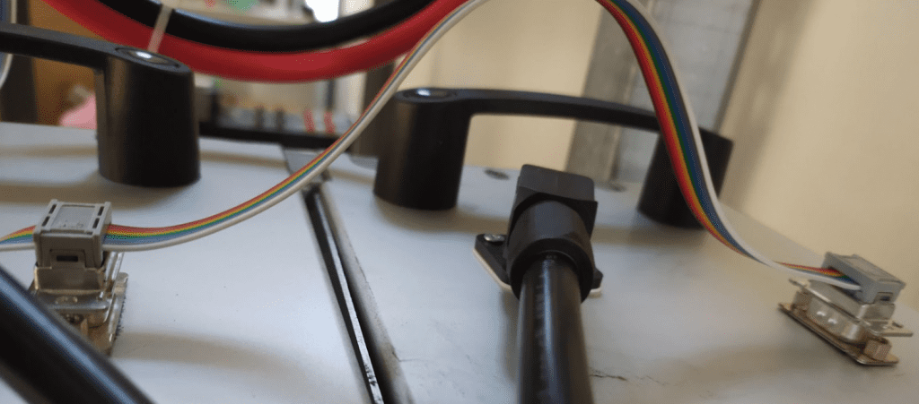
3.2.5 Communication layerings connection
Connect communication plugs (multicolored layering). The plug at the end of the layering must be plugged into the DB9 plug of the bottom battery and the other one into the plug closest to the front panel.
Warning
Make sure to correctly plug in the plugs.
3.3 Input / output requirements
Danger
There is a risk of high voltage electrical shock when the AEA operates. Only electriciens with professional skills can operate. All connections with this equipment must be done when the cabinet is powered down. The AEA can be damaged if the input or output terminal is not plugged in correctly. Non-compliance with those information can lead to serious injury, death and important material damage.
| Cable (Cu) | Cable section requirements (mm2) | Tightening |
| Earth | Minimum 6 mm². Green and yellow advised | ct > 8,20N*m |
| Photovoltaic | Minimum 4 mm² | ct > 8,20N*m |
| Cabinet supply | Minimum 2.5 mm² | ct >= 8,20N*m |
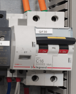
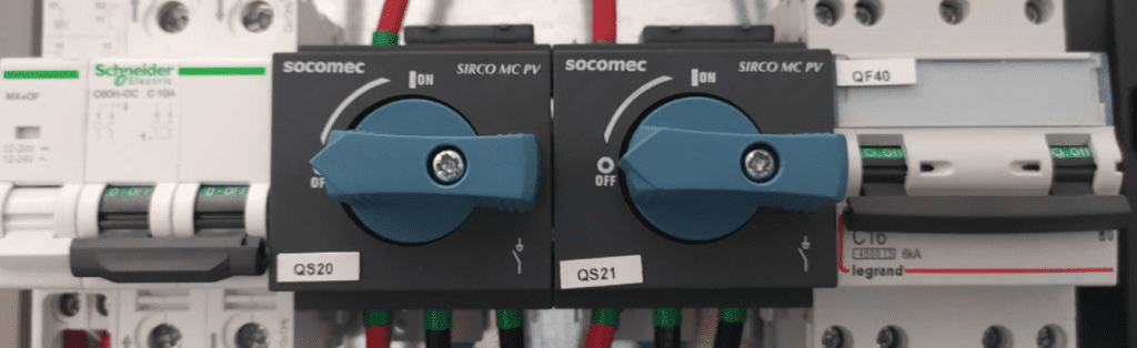
3.4 Circuit breakers for AEA 10000
- Schneider QF30 circuit breaker : battery outage
- QS20, 21 : photovoltaic disconnector
- QF40 : back-up output outage
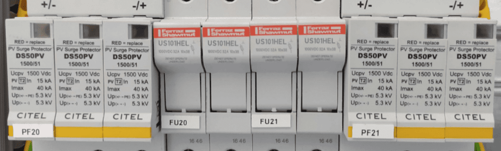
- PF20, 21 : lightning arrester PV
- FU20, 21 : fuses PV
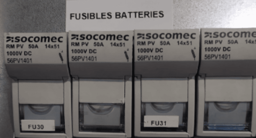
- FU30 and FU31 : Battery fuse holder
3.5 Grid connection
3.5.1 Connection for AEA3000 et AEA5000, single phase

Connect the cabinet to the grid as followed :
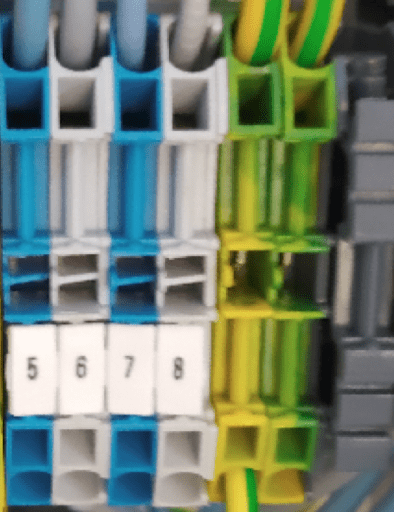
connect the neutral on terminal 1 of the XP terminal block, the phase to the terminal 2 and the earth to the plug next to the terminal.
3.5.2 Connection for AEA10000, single phase
A venir
3.5.3 Connection for AEA10000, three phase
Grid connection to the XP terminal : Neutral on terminal 1 ; phase 1 on terminal 2 ; phase 2 on terminal 3 ; phase 3 on terminal 4 ; earth on earth terminal (green and yellow)
3.6 Maesuring toroid connection
3.6.1 Connection for AEA3000 and AEA5000, single phase
Depending on the installation there is 2 different case :
With red and yellow wires :

Connect the toroid to the XTC terminal block, red wire to terminal 1 and yellow wire to terminal 2.
Attach the toroid to the customer arrival phase on the main housing line to monitor the consumption : the arrow inside the toroid must be directed toward the grid.
During the commissioning of the extension cord be careful to respect the following connections : red wire on the left and yellow wire on the right as pictured (maximum length 15m).
With black and red wires :

Connect the toroid on the XTC terminal block, black wire on terminal 1 and red wire on terminal 2.
Attach the toroid to the customer arrival phase on the main housing line to monitor the consumption : the arrow inside the toroid must be directed toward the customer consumption.
Attach the toroid to the customer arrival phase on the main housing line to monitor the consumption : the arrow inside the toroid must be directed toward the customer consumption.
3.6.2 Connection for AEA10000, single phase
A venir
3.6.3 Connection for AEA10000, three phase
Depending on the system you will have to connect toroids or not. Toroids connections are done using the XTC terminal at the bottom of the cabinet.
Avertissement
It is important to mind the direction of the toroids while connecting.
Depending on the installation there can be an XC terminal : XC1 and XC2 are controlled by a ralay to start the power generator automatically. When the charge status reaches 22% the contact between XC1 and XC2 will close. It will stay closed until the battery’s charge status reaches 60 % (adjustable).
3.7 Photovoltaic panels connection

Depending on the installation, the number of PV strings can change.
The specific procedure are :
- Cut off the voltage in the PV string at field level with the MC4 connectors. Check that there is no voltage in the cables on the DC side.
- Identify the positive and negative poles with a multimeter.
- Connect the first PV string to the MC4 connectors coming out of the cabinet identified as « String 1 ». The positive polarity should be connected to the cabinet’s red cable and the negative one to the black cable.
- Connect the second PV string on the MC4 connectors coming out of the cabinet identified as « String 2 ». The positive polarity should be connected to the cabinet’s red cable and the negative one to the black cable.
3.8 Betteries commissioning
Information
To be done when powering up : batteries are activated by switching on the QF30 circuit breaker. Batteries LED will be flashing and quickly be static green.
Warning
By switching on the circuit breaker you close the circuit and there is now a voltage at the terminal block XBA and at the QF30 terminals.
4. Option configuration
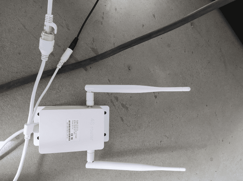
4.1 Router


The router must be powered with 12V with the cable coming from the XC terminal block. It must also be connected to the RJ45 cable. See picture.
Prerequesite
- Wifi connection available
- Have a computer or a smartphone
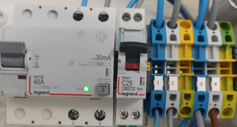
- ID10 circuit breaker is ON
- QF10 circuit breaker is ON
- WiFi indicator light is ON (green)

Step 1
Go to your computer or smartphone wifi settings to look for nearby networks. Select the router. It is named « AEA_21360xxx » (depending on the serial number on the cabinet). In the picture, after selecting « connect » a password will be asked. The password is the serial number of the AEA (2136xxxx).

Step 2
Once connected to the router, go on an explorer such as Mozilla, Explorer or Chrome. Enter on the top search bar : 192.168.100.1 and launch the research.

Step 3
The following page should appear.
You have to enter the password « admin » in the search bar and press on the « login » button.

Step 4
The following page should appear.
Click on « WiFi Settings ».

Étape 5
Go in the « Internet Wifi » tab.
And click on « Add ».

Step 6
Select the customer WiFi network in the list (bottom of the page) by clicking on the box left to the name. Then, enter the customer WiFi password in « Pass Phrase ». And click on « Apply »

Step 7
Check the box corresponding to the WiFi network and click on « Connect ». To check if your manipulations worked, make an internet research (it doesn’t matter what). If the research works it means the router configuration worked and the cabinet is connected to the Internet.
4.2 Resistive hot water tank management
4.2.1 Control of the hot water tank
With the AEA it is possible to control a resistive hot water tank to optimize the usage of photovoltaic energy.
If this option is activated the heating of the hot water tank will be the priority when discharging batteries. It means that the solar energy excess will be first used to heat the water tank.
The heating will be switched on when the photovoltaic production will be superior to the building consumption and only on peak hours. The heating power will be approximately equal to the production surplus. If there is no more surplus the heating will stop gradually by using the batteries as a power source.
The existing connector peak.off-peak hours will still be operational, it will control an internal connector inside the cabinet which will inhibit the dimmer. During off-peak hours the heating of the water tank goes back to the classic operational mode and does not use the dimmer.
Sufficient production for : 1. consumption / 2. hot water tank / 3. batteries
4.2.2 Hot water tank connection (20A max.)
Connect the hot water tank to the XP terminal block, neutral to the terminal number 5 and phase to the terminal number 6.
4.3 Energy selling to the grid
When this option is chosen the priority is to supply the needs of the building and the charge of batteries. If there is a production excess, instead of restraining the production, power will be redirected toward the grid. This option means you need to possess a contract to sell your power to the grid. To enable or disable this option you need to contact your installer.

The case of selling power to the grid : If the produced power is enough, the excess will be reinjected into the grid.
In the case were both options are enabled the priority order will be :
- Supplying building consumption
- Heating the water tank
- Charging the battery
- Selling to the grid
4.4 Back-up system
4.4.1 Back-up management system
The AEA has a back-up output. It ensures a temporary energy source in case of a power failure, intentional or not. This output is powered when the system is on sector undervoltage and stays on when the power input is cut off. Batteries take over the powering of the back-up output by supplying an AC voltage output (230VAC), similar to the sector input.
4.4.2 Back-up connection
Connect the back-up output to the XP terminal block, neutral to the terminal number 3 and phase to the terminal number 4.
AC casket connection
The connection of a back-up outputs needs an AC casket. Which is equiped with an earth-fault breaker and a circuit breaker.
- Connect the grid input : neutral terminal 1, phase terminal 2, earth on the terminal next to it
- Connect the terminal 3 of the casket to the terminal 1 of the AEA (neutral)
- Connect the terminal 4 of the casket tot the terminal 2 of the AEA (phase)
- Connect the last earth terminal of the casket to the earth terminal of the AEA.
4.5 Back-up casket
4.5.1 Commissioning of the back-up casket
Before activating the circuit breaker ahead of the casket, be sure the differential circuit breaker is on Off mode.
Activate the circuit breaker ahead of the installation then activate all other circuit breakers of the installation (Reconnect the differential circuit breaker if it trips).
Wait at least 1 minute and 30 seconds (after activating the circuit breakers) before checking if the back-up casket works.
To test the back-up casket, switch off the main circuit breaker and check if the loads supposed to be powered are still on. Reconnect the main circuit breaker and check if all loads are powered.
Without an AC casket
This casket allows you to change the power source in case of a power cut : electric grid or AEA’s backup output.
Refer to the following layouts for the wiring :

With an AC casket
If you have the AC casket option and the back-up casket option please refer to the following wiring :

Depending on the installation the AC casket can be included in the back-up casket (differential circuit breaker and 16A or 25A circuit breaker in the back-up casket) :

5. Implementation
5.1 Power up / power down for AEA3000 and AEA5000
Inter-disconnectors up front are disconnectors with multi poles usable for emergency shutdown as well as complete shutdown of the cabinet.
Outage devices up front are preferably open when the cabinet is powered down.
Powering up
- Activate QF10 (inverter input circuit breaker)
- Activate QF11 (if present)
- Activate QF30 (battery circuit breaker)
- Activate QF20/21 (photovoltaic circuit breaker)
Powering down
- Switch off QF10 (inverter input circuit breaker)
- Switch off QF11 (if present)
- Switch off QF20/21 (photovoltaic circuit breaker)
- Switch off QF30 (battery circuit breaker)
Danger
There is still voltage in the XP terminal block. That is why the power supply  must be cut off before.
5.2 Power up / power down for AEA10000
Powering up
first time :
- Check that the emergency stop button is not pushed in.
- Switch on all circuit breakers. The “Under-voltage” light should be ON.
- Check that the default light is off.
Powering down
- Switch off the photovoltaic DC circuit breakers.
- Switch off the AC circuit breakers if there is a connection to the grid.
- Switch of QF30 circuit breaker (if present).
Danger
Once the cabinet is off, wait at least 5 minutes before intervening
5.3 Check the proper functioning
To check the proper functioning, you will have to check if the information on the MyHome&Me app (https://myhomeandme.fr/) are present and consistent.