
Last update on
- 1. Introduction
- 2. Characteristics
- 3. Connections
- 4. Safety and warnings
- 5. Protection device
- 6. Elimination
- 7. Cleaning
- 8. Technical features
1. Introduction
This manual describes the specific features of the MicroARM-A12 (SAV1288 card).
For information common to programming, see the “MicroLADDER manual”. To visualize better the corresponding addresses in MicroLADDER, they appear in color, on the sides of the diagrams.
2. Characteristics
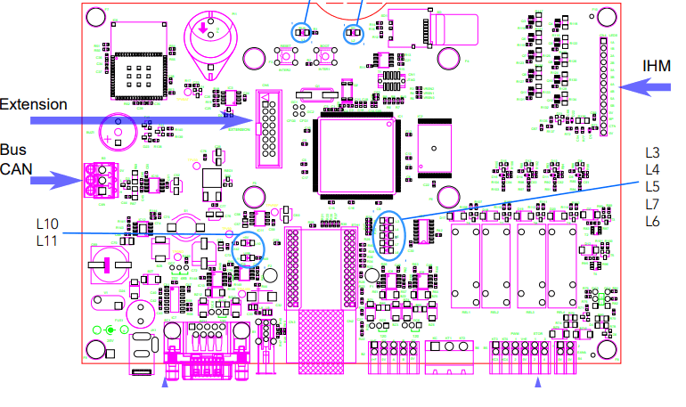
2.1 Board presentation
Supply voltage: 24 V. The board can operate in 12 V, but the digital relay outputs do not work.
- ARM7 LPC1788 Cortex Processor
- 512Ko Flash (to save the monitor and the application)
- 2 Mo of saved RAM
- 1 internal to the processor RTC (Real Time clock) with backup battery
- 1 RS232 or RS485 port (configuration per jumper) (COM0) on SubD connector port for loading or free of use
- 2 RS485 (COM1 and COM2) ports with end of line resistance for loading or free of use
- 1 RS232 TTL communication port (optional on the extension connector)
- 1 SPI communication port (optional on the extension connector)
- 1 I2C communication port (optional on the extension connector)
- 1 CAN communication port (optional)
- 1 Ethernet connector with 4 autonomous communication
- 1 WIFI module
- 1 connector for the micro SD card (the card must be formated in FAT32)
- 1 USB port
- 4 digital inputs 24 V
- 2 analog inputs (0-10 V or 0-20 mA – 24 bytes configurable by jumper)
- 2 PWM outputs with transistor 24 V
- 2 relay outputs with a commun point 250 V – 2 A
- 2 relay outputs 160 V – 4 A
- 1 BP inputs (on the Human-Machine Interface (HMI) connector)
- 1 CTN 10Kinput (on the HMI connector)
- 10 LED outputs to manage 5 bicolors LED (on the HMI connector)
- 1 buzzer
- 1 reset push-button (inter 2)
- 1 push-button to change the program (inter 1)
2.2 LED meanings
| L1 | Working state of the PLC |
| L2 | Presence of a SD card |
| L3, L4, L5, L6 and L7 | Ethernet (non mounted LEDs) |
| L10 | Presence of a 5V tension |
| L11 | Activity on the USB port (non mounted LEDs) |
See blue circles on drawing in section 2.1
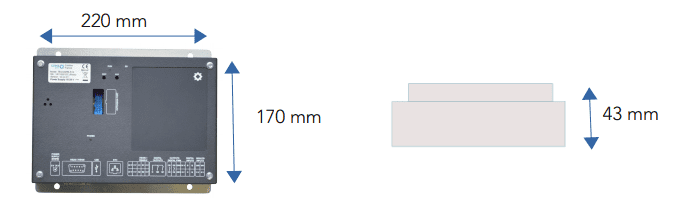
2.3 Dimension
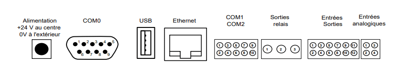
3. Connections
3.1 Digital
3.1.1 Digital input
% I100 to% I103 are digital inputs. The input must be connected to + 24 to mount the
input to 1.
3.1.2 Digital output
% QW100 and% QW101 are PWM-to-transistor outputs. The load must be connected
between the output and the mass.
% Q100 and% Q101 are 2 potential free relay outputs, but there is a common contact to both outputs. Maximum 250 V – 2 A. The 2 A can be used at the same time on both
outputs.
% Q102 and% Q103 are 2 potential free relay outputs. Maximum 160 V – 4 A.
 | 1 :Common free of potential, but common to the 2 outputs 2:% Q100 relay output 3:% Q101 relay output | 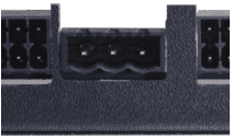 |
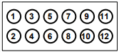 | 1 : Contact 1 %Q102 2 : Contact 2 %Q102 3 : Contact 1 %Q103 4 : Contact 2 %Q103 5 : %QW100 6 : %QW101 7 : + 24 V supplied by the board 8 : Mass 9 : %I100 10 : %I101 11 : %I102 12 : %I103 | 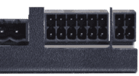 |
3.2 Analog
3.2.1 Analog input
They can be configured in 0 – 10 V or 0 – 20 mA using the GC3 jumpers (for% I100) and GC4 (for% I101).
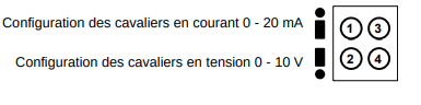 | 1 : %IW101 2 : Mass 3 : %IW102 4 : Mass | 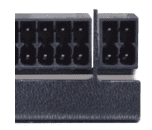 |
3.3 Communication port
3.3.1 COM0 RS232 or RS485
The COM 0 can be configured in RS232 or RS485 using the GC7 jumper located 2 cm above the Sub-D connector.
The GC8 jumper allows to activate the end-of-line resistance for RS485 mode.
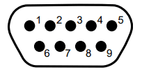 | 1 : Free 2: RX (Standard pin-outs) 3: TX (Standard pin-outs) 4: A-RS485 5: Mass (standard pin-outs) 6: Free 7: RTS (Standard pin-outs) 8: CTS (Standard brachage) 9: B-RS485 |  |
3.3.2 COM1 and COM2 RS485
The GC5 jumper allows to activate the end line resistance.
The GC6 jumper allows to activate the end line resistance.
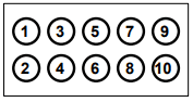 | COM 1 1 : +24 V supplied by the board 3 : Mass 5 : A 7 : B 9 : Mass | COM 2 2 : + 24 V supplied by the board 4 : Mass 6 : A 8 : B 10 : Mass | 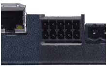 |
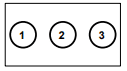
3.3.3 CAN Bus
This communication bus is optional
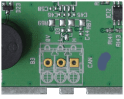

1 : CAN-H
2 : CAN-L
3 : Mass
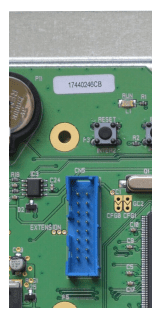
3.3.4 Extension
The optional mounted Extension connector has a TTL RS232 port, an SPI bus, and a I2C bus.
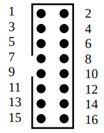 |  |
| 1 : 5V DC 2 : Power supply 3 : 33V DC 4 :0V 5 :0V 6 :0V 7 : /RFU_CS2 8 : RFU_CLK2 | 9 : RFU_MISO2 10 : RFU_MOSI2 11 :RX3 12 :TX3 13 RFU_SDA1: 14 : RFU_SSL1 15 : RFU_CAP0.0 16 : RFU_PWM0.6 |
3.4 HMI
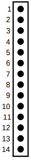 | 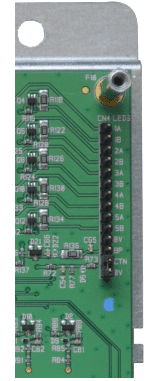 |
1 : %Q2 LED 1A
2 : %Q3 LED 1B
3 : %Q4 LED 2A
4 : %Q5 LED 2B
5 : %Q6 LED 3A
6 : %Q7 LED 3B
7 : %Q8 LED 4A
8 : %Q9 LED 4B
9 : %Q10 LED 5A
10 : %Q11 LED 5B
11 : Mass
12 : %I0 BP (the input must be linked to the mass to mount %I0)
13 : %IW100 CTN de 10 K (the other extremity of the CTN must be linkec to the mass). The temperature is read directly in tenth of a °C.
14 : Mass
%Q1 : buzzer
3.5 Power supply

4. Safety and warnings
Warning
If the device is not used as per these instructions, the safety of people and equipment can be compromised. We disclaim any liability for any material damage or due to improper handling or failure to comply with the safety instructions.
The interventions on the devices must be made by staff who are competent to work on electric installations.
Before all interventions, all power supplies must be switched off. The cutting devices on the installation must be dimensioned and placed according to the standard UTE C
15-100.
For all interventions on a device installed on an electric installation, the Personal Protective Equipment (PPE) as defined by the safety regulations on the electric installations must be carried by the worker.
In the event of a failure or malfunction, the device must not be opened and must be
returned to the factory.
Observe the following pictograms :
 | Warning. On the product label this symbol means that the notice must be consulted. In this manual, this symbol indicates important information. |
 | Direct current. |
 | This device is CE approved and complies with the national and European guidelines. |
5. Protection device
Quick fuse protections must be positioned on the 24 volt continuous start feeding the PLC. These fuses will be sized according to the number of devices set in series behind the start.
6. Elimination

Old electronic devices are recyclables goods that should not be thrown into the trash can. If the device reaches the end of its life, it should be eliminated in accordance with the legal regulations in force to the recovery centres in your municipality. Elimination in the household trashes is prohibited.
7. Cleaning
For cleaning, use a clean, dry, antistatic, lint-free cloth without corrosive products.
8. Technical features
| Power supply | 18 to 28 V |
| Maximum operating Altitude | 2000m |
| Maximum operating Temperature | 45 °C |
| Maximum Operating Humidity | 70 % |