
Last update on
- 1.Targeted readers
- 2.Installed version
- 3. Installation
- 4. Getting to know the interface
- 5. Programming on MicroLADDER
- 6. Software environment
- 7. IO Bus
- 8. HTTP Protocol
- 9. Wi-Fi
- 10. Connection to a server
- 11. Log management
- 12. Miscellaneous information
1.Targeted readers
This documentation is intended for users of the MicroLADDER software, which allows you to program all the PLCs in the SIREA range. The particularities of each PLC are described in their respective manual.
2.Installed version
This notice is for MicroLADDER version 18.3.
Disclaimer
It is important to note that this notice is for the latest version of MicroLADDER. Over the years modifications/improvements have been made. If you install an earlier version, you may find that this documentation is no longer entirely valid. Some notes ("valid since version …") have been added to try to help you if you use an earlier version.
3. Installation
To install the MicroLADDER software, several operations must be carried out so that it functions correctly. Several entities must be installed. The following table describes the entities and their use.
| Entity | Utility |
| Compiler | The role of this software is to search for all possible errors in a source program, such as spelling mistakes, variables, types, etc. |
| MicroLADDER | This software is used to build the application, compile it, do dynamic visualization and variable forcing. |
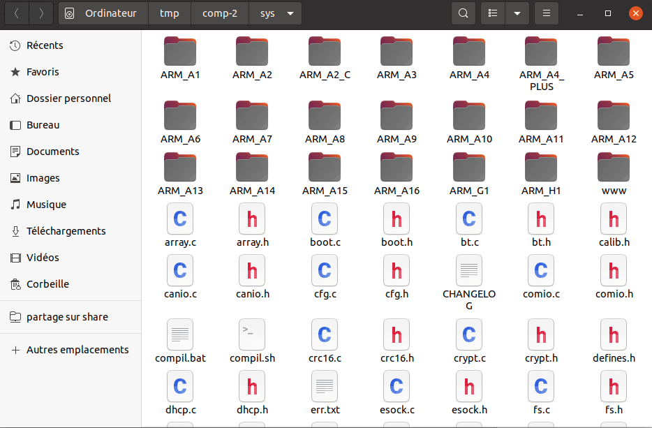
| System code | The system code is an archive that gathers all the macros and functions (in .h and .c files) that make the PLCs work. These macros and functions can be used in the programs. It is also used to manage the hardware side with the different inputs/outputs of the PLCs |
| MicroCONTROL | This software is used to load the application, do dynamic visualization and forcing. |
| MicroDRIVER | This software is used by MicroCONTROL and MicroLADDER for communication with the PLC. |
3.1 Step 1: Compiler Installation
3.1.1 Under Windows operating system
For Windows, run the installation file “gcc-arm-none-eabi-4_9-2015q1-20150306-win32.exe” by double clicking on it.
Check “Add path to environment variable” at the end of the installation and close the command window that remains open.
Warning
Under Windows 7, you must install the compiler from the administrator account and give access to all users.
3.1.2 Under Linux operating system
First open a terminal.
Type in the terminal “sudo apt-get install gcc-arm-none-eabi”. This will install the version of the GCC compiler compatible with the Linux distribution.
To know the installed version, type in a terminal “arm-none-eabi-gcc –version”.
3.2 Step 2: MicroLADDER installation
3.2.1 Under Windows operating system
To install it, under Windows, you have to execute the file “setup-mladder-x.x.exe” by double clicking on it.
3.2.2 Under Linux operating system
Open a terminal.
Type and execute the command “sudo dpkg -i mladder-x.x.deb”. “x.x” corresponds to the chosen version.
If the installation does not work because of lack of dependencies, it is necessary to run the command “sudo apt-get -f install”.
3.3 Step 3: System Code Installation
Open the MicroLADDER software with the following icon:
The following window opens:
In the “Program” tab, click on “Import system code”. A popup window will open. Search and select the file “mArm.sys”.
Warning
The choice of system code must be made according to the version of the boot installed on the card and the version of MicroLADDER.
Information
This step is optional. Indeed, during the execution of a program, a system code will be fetched (the system code having the most recent version). However, some problems can occur because this system code is remote and not on your machine. It is therefore strongly recommended to install the system code.
3.4 Step 4: MicroCONTROL Installation
3.4.1 Under Windows operating system
To install MicroCONTROL, run the file “setup-mcontrol.exe” by double clicking on it.
3.4.2 Under Linux operating system
Open a terminal.
Type and execute the command “sudo dpkg -i mcontrol.deb”.
3.5 Step 5: MicroDRIVER Installation
3.5.1 Under Windows operating system
To install it, under Windows, you have to run the file “setup-mdriver.exe” by double clicking on it.
3.5.2 Under Linux operating system
Open a terminal.
Type and execute the command “sudo dpkg -i mdriver.deb”.
3.6 Step 6: Restart your computer
The last but simplest step is to restart your computer.
4. Getting to know the interface
4.1 Launch and exit MicroLADDER
To start the program, double-click on the MicroLADDER icon.
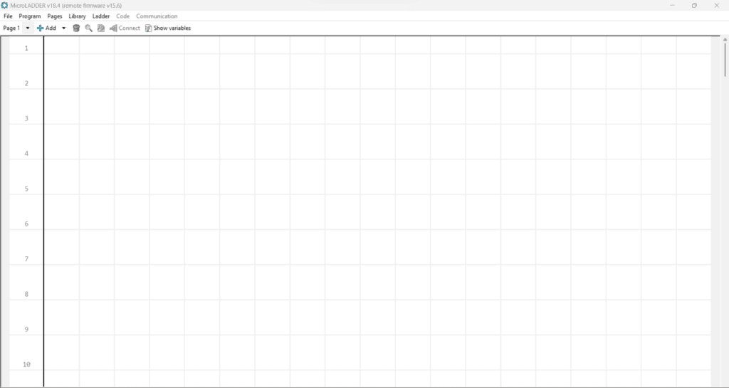
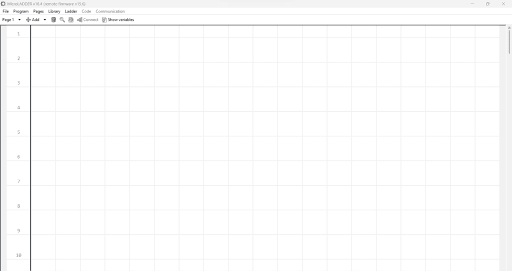
The MicroLADDER program opens with the following main window:

To exit the program, click either on the “Close” icon (the red cross at the top right) or go to the menu bar then File>Exit.

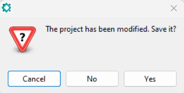
A popup window will open asking us if we want to save the changes that have been made to our program. If you click on “No” then you will lose any last unsaved changes.
If we click on “Cancel”, it will not close the program anymore.
4.2 Features of the main window
The following items can be found on the main window:
- Title bar: here you can find the version of MicroLADDER installed. In the example of the screenshot below, you can see “MicroLADDER v18.3”. It also indicates whether you are using the remote or embedded system code. Here, the remote system code v15.6 is used.
- Menu bar: here you can find the tabs:
-File
-Program
-Pages
-Library
-Ladder
-Code
-Communication - Toolbar: The toolbar includes the following items:
– Page selector
-“Add” button
-“Delete” button
-“Search” button
-“Search and replace” button
-“Connect” button
-“Display variables” button - Programming window: this window delimits the space for programming. You can move around this window using the scroll bar on the right side.

4.3 Menu bar
The MicroLADDER menu bar contains a series of drop-down menus that can be used to access the various tools and configuration utilities of the program.

The following drop-down menus in order from left to right are included in the menu bar:
4.3.1 File (Alt+F)
The following features and their shortcuts (explained in brackets) are available:
- New (Ctrl+N): creates a new project. If you already have a project open, you will be asked whether or not to save the changes.
- Open (Ctrl+O): opens an existing project. A popup window for selecting the file in your folders will appear.
- Save (Ctrl+S): saves the changes to the open project with the predefined name and location. If the project you are working on has not yet been opened, a popup window opens to select the location where you want to save the file. A .lad file will then be saved in the specified location. An asterisk in the title bar next to the system code version indicates whether the last changes made to the current project have already been saved (without asterisk) or not (with asterisk).


- Save as: saves changes to the project by choosing the name and location in a popup window. The five most recent projects will also be displayed in this menu for easy access.
- Quit (Ctrl+Q): quits MicroLADDER. If you have not saved the changes manually, a popup window will appear asking if you want to save. If you click on “No” then all the last unsaved changes will be lost. If you click on “Cancel”, you won’t close the program anymore.
4.3.2 Program (Alt + P)
- Compile: compiles a program. After compiling, a new popup window will open allowing you to choose a location to save it.
Warning
To compile, the system code must first be imported into the project or be available online (step 3 of the installation).
- Define program type: selects the type of program to be developed, either a function block or a specific PLC program:
– µArm A1
– µArm A2
– µArm A2-C
– µArm A3
– µArm A3-B
– µArm A4
– µArm A4+
– µArm A5
– µArm A6
– µArm A7
– µArm A8
– µArm A9 A
– µArm A9 B
– µArm A10
– µArm A11
– µArm A12
– µArm A13
– µArm A14
– µArm A15
– µArm A16
– µArm G1
– µArm H1
Warning
Please note that the system code must be imported to see all the options of the program types to be created. If the system code is not imported, only the "Function block" type is available.
- Set icon: associates an icon with the project. This icon will appear in the window icon instead of the MicroLADDER icon. This function is available for both PLC programs and function blocks. On the other hand, it is more useful to define an icon for a function block because an image of the block will be displayed when it is imported into a project and called up on a Ladder page.
- Devices: gives the list of devices, divided into two types:
-Basic equipment: this option creates a list of parameters that will allow the configuration of the data feedback to the server.
-Add remote equipment: this option allows you to define the slave(s) used to create a Modbus network (see section 7. IO Bus).
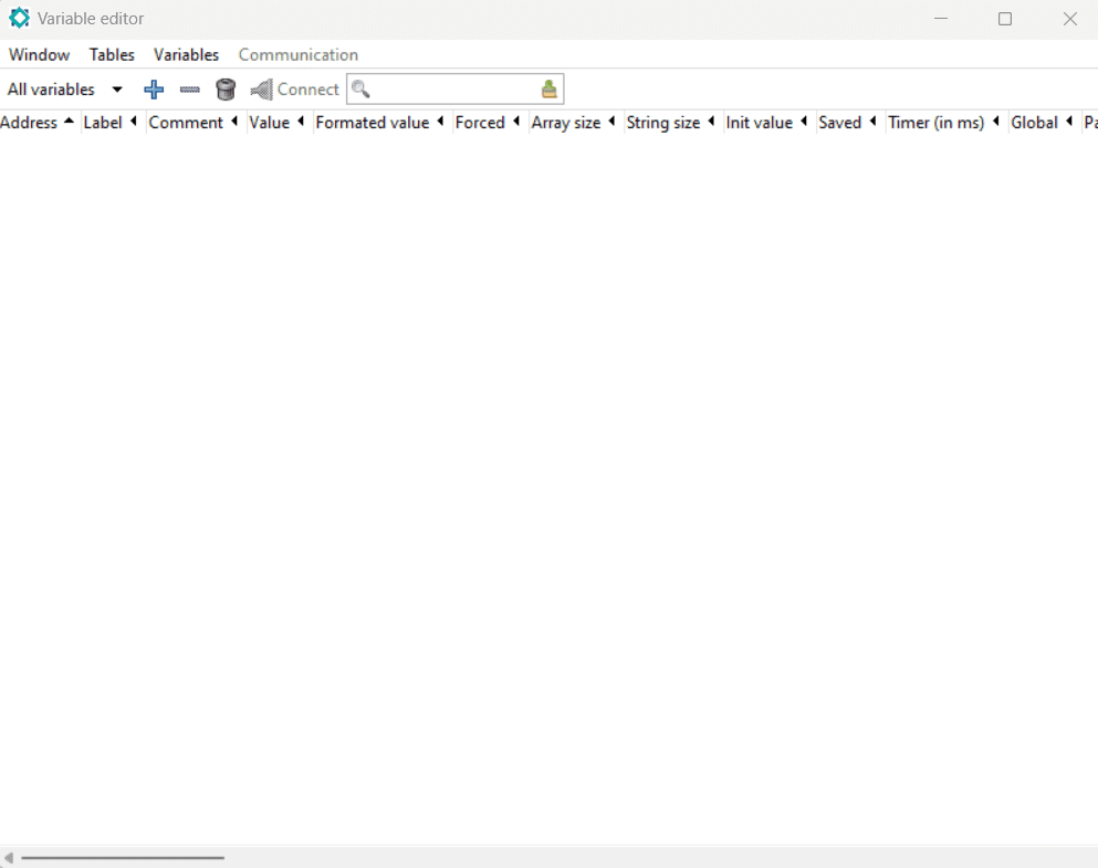
- Show variables: this option opens the variable editor window. This window contains all the information about the program’s variables, both system variables and user variables. This window is also used to check the real time value of the variables when communicating with the PLC. This option can also be accessed using the “Show variables” button located on the toolbar.
- Configure system code: configure options for the compilation. Click on this option to modify the system code parameters by selecting the ones we are interested in:
– AUTO-STOP (default)
– DHCP (default
– DNS (default)
– GFX
– HTTP
– LCD (default)
– RF
The explanation for each parameter is in section 6.4 System code configuration. - Import system code: before creating a new program, the system code must be imported. Click on this option, a popup window will open, allowing us to select the mArm.sys file. Once the system code has been correctly imported, the different options for the program type will be available.
If you have an Internet connection, you do not need to import the system code because MicroLADDER will use the system code online, but this is not recommended. - Export system code: this option allows you to export the system code currently imported into the project, in order to use it in other projects. You can use this option to develop a new program using the same system code, or simply to know the version of the system code of a PLC.
- Delete system code: This option allows you to delete the previously imported system code.
- Configure HMI: configure the options for the HMI.
- Import HMI: this option allows you, if you have created an HMI with MicroHMI, to include it in the current project.
- Export HMI: this option allows you to export a previously imported HMI.
- Delete HMI: this option allows you to delete a previously imported HMI.
4.3.3 Pages (Alt+G)
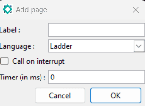
- Add a page: adds a new page to your current project. A popup window opens. The following fields are available:
-“Label”: string of characters of the name that the page will take. If you don’t fill this field a label will be created automatically by assigning a number to the page
-“Language”: drop-down menu allowing to choose Ladder or C. By default the language is Ladder.
-“Call on interrupt”: fields to check if you want the page to be called by an interrupt
-“Timer (in ms)”: integer indicating the time (in milliseconds) after which the page will be called by an interrupt
- Modify this page: this option allows you to modify the fields explained just above a specific page already created.
- Duplicate this page: duplicates the page you are on. The properties and the code will be kept in this new page.
Information
Note that the new page added will have a label automatically created by assigning the next available page number to the new page. If the duplicated page had a label then the new page will not have that label.
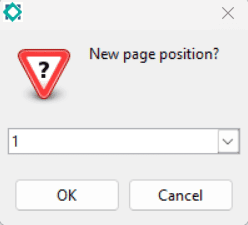
- Move this page: Moves the page we are currently on. By clicking on this option, a popup window will open asking us to select the new position of the page through a drop-down menu.
- Delete this page: deletes the page you are on. A new window will open to confirm the deletion of the page. If you want to delete the page, click on “Yes”, otherwise close the window or click on “No”.

- Page 1 (and following): list of the different pages available in the project directly accessible from this menu.
4.3.4 Librairie (Alt+L)
- Import a function: import a function into the current project by selecting it in the popup window that appears.
- Export a function: exports a function to the current project by selecting it in the new popup window that appears.
- Delete a function: deletes a function from the current project by selecting it in the new popup window that appears.
4.3.5 Ladder (Alt+D)
Warning
This drop-down menu will not be accessible from a C page.
- Select All (Ctrl+A): this option allows you to select all the elements included in an active page.
- Reverse selection (Ctrl+Shift+I): this option allows you to select the elements that are not currently selected (reverse selection). If no element is selected, then all elements will be selected by clicking on this option.
- Cut (Ctrl+X): this option allows you to cut one or more elements. Once you have selected the element(s) you wish to cut, click on this option. The selected element(s) will not disappear or change its appearance to indicate that it is being cut. It (They) will simply disappear from its (their) previous position when you paste it (them). You can also cut the item(s) by selecting this option from the context menu.
- Copy (Ctrl+C): This option is used to copy an item or items. Once you have selected the item(s) you wish to copy, click on this option. You can also copy the item(s) by selecting this option from the context menu.
- Paste (Ctrl+V): this option allows you to delete one or more elements from the page. Position the mouse cursor where you want to paste the previously cut or copied element(s). You can also paste the element(s) by selecting this option from the context menu.
- Delete (delete): this option is used to delete one or more elements from the page. Once you have selected the element(s) you wish to delete, click on this option. You can also delete the element(s) by selecting this option from the contextual menu or by using the “Delete” button placed in the toolbar.this button is activated when there is a selection.
- Properties: this option allows you to assign the variable or the code associated with the selected element (only one element at a time). The variable can be assigned with both the address and the mnemonic. The properties of the element can also be accessed by selecting this option in the context menu or by double-clicking on the element. Note that the double-click only works if MicroLADDER is not connected to the PLC. If there is a connection then the double-click allows you to force the value of a variable.
- Add: This option is used to add a new element to the current Ladder page. Simply select the desired element from the drop-down menu and place it with the mouse cursor at the desired location by a simple left click. You can also add elements from the context menu or by using the “Add” button in the toolbar. When accessing from the context menu, be sure to place the mouse cursor in the desired location first before right-clicking, as the item will be placed directly without the need for an additional left click.
4.3.6 Code (Alt+O)
Warning
This drop-down menu will not be accessible from a Ladder page.
- Search (Ctrl+F): this option from a C code page activates the search bar for code search. This bar will appear at the bottom of the window. Type the text to be searched in the search bar and activate “Match case” for a case sensitive search and “Wrap around” if you want all matches on the page to be marked.

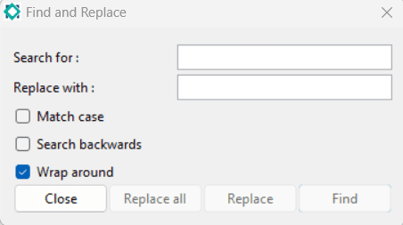
- Search and replace (Ctrl+R): this option from a C code page opens a popup window. Then specify the search criteria and the replacement text. You can either manually replace a single part of a text or replace all of it. In the case of a manual replacement, you can also do it forwards or backwards, by activating or deactivating the Search backwards option.

4.3.7 Communication (Alt+C)
Information: This drop-down menu will not be accessible from a function block but only from a PLC program.
- Connect: this option is available when no connection has yet been established. A popup window ‘Connect to MicroDRIVER’ will appear when this option is clicked on. Several fields (communication method, slave number and MicroDRIVER address) must be filled in to connect to the controller. You can also access the “Connection to MicroDRIVER” window using the “Connect” button in the Tools menu. For further information on how to establish a connection, refer to section 5.3.2 Establishing a connection.

- Disconnect: this option is available when a connection has already been established. By clicking on this function the communication with the PLC will be stopped.
- Read slave number: this option is only available when a connection to a PLC has been established. It is used to obtain the slave number of a specific slave, when it is planned to connect several of them in series on the same line.
- Write slave number: this option is only available when one (and only one) connection with a PLC has been established. It allows to modify its slave number.
- Program start: this option starts a program when the PLC is in the STOP state. A popup window appears indicating that the program has started.
- Program stop: this function stops a program when the PLC is in the RUN state.
- Reset equipment: this option resets the PLC to its BOOT state. It is useful to test its reactions when it is switched on and off for example.
- Reset variables: this function resets all variables to their initial values and does not stop the program. The PLC is always in the RUN state. It is useful to simulate a behavior.
- Loading a program: this option opens a popup window “Loading a program” allowing us to choose the hexadecimal file (.hex) that we want to load on the PLC. This action takes several tens of seconds, so it is faster to load using an SD card if the PLC has an SD card reader.
Information: It is possible to know the corresponding key associated with the Alt+key shortcuts for direct access to each drop-down menu in the menu bar by clicking Alt while the menu bar is active or visible. The letters associated with each key will appear underlined.
4.4 Toolbar
The toolbar is located at the top of the main window.

The following items are included in the toolbar:
- Page selector: this option opens a drop-down menu to select the page you wish to work with.
- Add: This option is used to include a new ladder element on the current page. Simply select the desired element from the drop-down menu and place it with the mouse cursor at the desired location by a simple left click. You can also add items from the menu with a right click. When accessing the menu by right-clicking, be sure to first place the mouse cursor at the desired location before right-clicking. The item will be placed directly without the need for an additional left click.
- “Delete” icon: this button is activated only when an item is selected on the page. Once the item(s) you wish to delete are selected, click on this icon. You can also delete the item(s) by selecting this option from the right click menu.
- “Search” icon: this option from a C-code page activates the search bar for the code search. This bar will appear at the bottom of the window. Type the text to be searched in the search bar and activate “Case sensitive” for a case sensitive search and “Wrap around” if you want all matches on the page to be marked.

- “Search and replace” icon: this option from a C code page opens a popup window. Then specify the search criteria and the replacement text. You can either manually replace a part of a text in one place or replace all of it. In the case of a manual replacement, you can also do it forwards or backwards, by enabling or disabling the Search backwards option.
- Connect: this option is available when no connection has yet been established. A popup window ‘Connect to MicroDRIVER’ will appear when this option is clicked on. Several fields (communication method, slave number and MicroDRIVER address) must be filled in to connect to the controller. You can also access the “Connection to MicroDRIVER” window using the “Connect” button in the Tools menu. For further information on how to establish a connection, refer to section 5.3.2 Establishing the connection.
Before this step, you must have selected the type of controller and then connected to the controller.

- Show variables: this option opens the variable editor window. This window contains all the information about the program’s variables, both system variables and user variables. It can also be used to check the real time value of the variables during communication with the PLC. This option can be accessed from the “Program” menu located in the menu bar.
4.5 Programming window
The programming window is the large empty space below the toolbar used for program development. Two types of programming windows can be displayed:
– the Ladder window
– the C window

5. Programming on MicroLADDER
5.1 Programming languages
5.1.1 Ladder language
The initial idea of the Ladder is the representation of logical functions in the form of electrical diagrams. This representation is originally material: when the programmable logic controller did not exist, functions were realized by wiring. The ladder was created and standardized in the IEC 61131-3 standard. It is still often used today in the programming of PLCs
A ladder program is read from top to bottom and the values are evaluated from left to right. The values correspond, if compared to an electrical schematic, to the presence or absence of an electrical potential at each connection node. The ladder is based on the principle of a voltage supply represented by two vertical lines connected horizontally by coils, contacts and function blocks, hence the name “ladder”. The language is deliberately simple and graphic in order to be understandable. This allowed, in the 1990s, its use without extensive training by electricians.
5.1.2 C language
The C programming language was originally developed by Dennis Ritchie between 1969 and 1973 at Bell Laboratories. It is suitable for writing system-level programs because of its simplicity of expression, compactness of code, and wide range of applicability. It allows the programmer a wide range of operations from high level to low level approaching assembly language level. The available flexibility is wide, which makes it a perfect programming language for the development of highly complex PLC programs.
5.2 Importing the firmware
With this version of MicroLADDER, the firmware is online and works automatically with your system. No import is required, but an Internet connection is.
5.3 Connection to the PLC
A connection to the PLC is required when loading a program via a port and when monitoring variables when the PLC is in RUN.
5.3.1 MicroDRIVER
MicroDRIVER is the software responsible for establishing the connection between the PLC and the various applications in the system. It can be considered as a “black box” of communications. It is independent of the system’s communication protocol.
The user will not be aware of its operation because it runs in the background. However, if MicroDRIVER is not installed, it will be impossible to establish a connection with the PLC.
5.3.2 Establishing the connection
To establish the connection between MicroLADDER and the controller, first click on the “Connect” option on the toolbar. Once this option has been selected, a connection popup window appears.
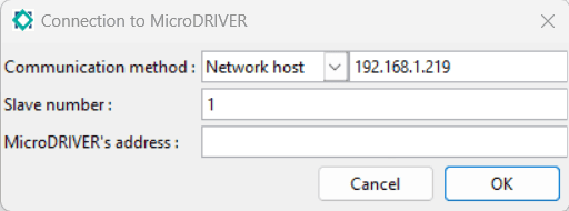
For the connection with MicroDRIVER, several fields must be filled in:
- Communication method: several communication methods are available:
-Network host: the connection is established through the network. The IP address or the domain name of the host is to be filled in the field on the right of the drop-down menu. The network host can for example be our computer.
-Serial port : choose a serial port in the list and its configuration
-Channel : obsolete feature
- Slave number: This number identifies the PLC within a network of PLCs. You do not need to define the slave number if you are programming a single PLC. It will be determined after the first connection.
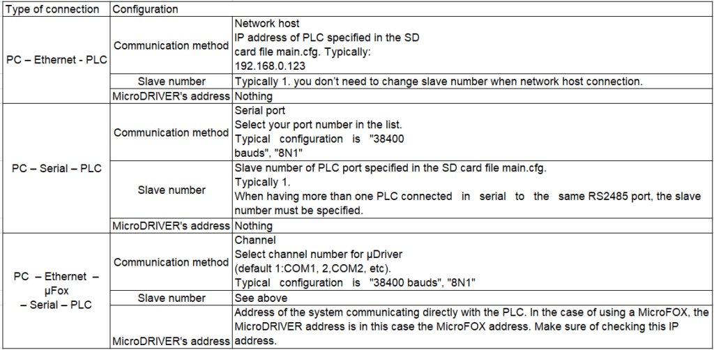
- MicroDRIVER address: MicroDRIVER is the server application. It can run locally or on a remote computer. If it runs on a remote computer, it is necessary to specify the IP address of that computer. The configuration of the connection to the MicroDRIVER may differ depending on how you connect to the PLC from your computer. The most common configuration parameters can be seen in the table below:
Once the connection parameters have been correctly filled in, click on “Validate” and the connection will be established. You can ensure that the connection has been established by checking the following:
- The “Connect” button in the toolbar is pressed (if you click on it, you directly disconnect again).
- The “Connect” option in the “Communication” drop-down menu of the menu bar is disabled and the “Disconnect” option is available.
- A green “OK” message appeared on the toolbar.
- Active program conditions also appear in green on the Ladder pages
Information
A percentage is displayed in green next to the connection status. This is simply additional information which shows the quality of the connection with the controller: it represents the percentage of frames which have been correctly transmitted. The calculation of this percentage starts at the same time as MicroDRIVER.
5.4 Using the pages
The number of pages that can be used in any MicroLADDER program is unlimited. Each Ladder page is limited to 100 lines, whereas C pages are not subject to this limitation. The limitation on the number of lines within a page in Ladder forces the user to structure the program in different pages and/or to use functions, which makes the code easier to interpret.
Page 1 is called at each PLC cycle but other pages can be called easily. It can be decided whether a specific page should be programmed in Ladder or in C. Pages from different programming languages can be called and combined easily. This gives the user a lot of flexibility and easy interpretation of the structure when creating applications. Make sure that there is no code already generated in a page when switching from C to Ladder or vice versa, as it will be lost.
5.4.1 Create a page
A new MicroLADDER project includes by default a single page (Page 1) which is configured by default in Ladder. It is possible to modify it by going to the “Page” drop-down menu in the menu bar and clicking on “Modify page”.
An additional page can easily be created by adding a new page or by copying an existing page (see section 4.3.3 Pages (Alt+G) for more information).
5.4.2 Calling a page
Page 1 is called automatically while the other pages must be called on interrupt, timer, or with call commands in C or Ladder.
5.4.2.1 BY INTERRUPTION
It is possible to call pages on interruption, so the page will be called at a certain frequency. This frequency is set in the system variable %SW25 for a precise and fast duration.
Information
It is advisable to call pages by interruption when they perform fast and repetitive tasks.
5.4.2.2 By timer
It is also possible to call a page via a timer. We will define this timer in the settings of the page property. At each PLC cycle, the PLC will check if its execution time is greater than the timer defined on the page. If it is greater then the page will be executed.
Information
It is advisable to call pages by timer when they run slowly and there is no need for them to be executed every cycle.
5.4.2.3 By call order C or Ladder
A page can be called from another page within a program, regardless of the type of code used in each page. This means that a ladder page can be called from a C page and vice versa.
To call a page in Ladder, simply add a call command either from the “Ladder” drop-down menu on the menu bar or from the context menu.
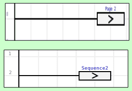
If the called page does not have a label, it will be called by its page number. In this example, Page 2.
If the called page has a label, it can be called either by its page number or by its label. However, in Ladder it is the label that will be displayed instead of the page number. This can be seen with the call of the page whose label is “Sequence2”.
In a page written in C language, another page can also be called either by its number or by a label.
page_2(); //To call up page 2
Sequence2() ; //To call the page named "Sequence2".
5.5 Manage variables
5.5.1 Variable editor
Variables in MicroLADDER are storage locations with an associated mnemonic that contain a known or unknown quantity of information.
The variables available in a MicroLADDER program can be displayed and modified from the variable editor.
5.5.1.1 Menu bar of the variable editor
The variable editor has its own menu bar, each with a drop-down menu.

These drop-down menus contain the following options:
5.5.1.1.1 Window
- Close: you can close the variable editor by clicking on this option or simply by clicking on the close button at the top right
5.5.1.1.2 Tables
- Add a table: in MicroLADDER a category or group of variables is called a table. By default MicroLADDER considers two tables: user variables and system variables. New tables can be defined by clicking on this option and giving a name.
- Rename this table: click this option to rename a table. Default tables cannot be renamed.
- Delete this table: click this option to delete a table. Default tables cannot be deleted.
- Import variables into this table: click on this option to import a CSV file of variables into the current MicroLADDER project.
- Export variables from this table: click on this option to export a table of variables in a CSV file from the current MicroLADDER project.
- Import values into this table: click on this option to import values into a table from the current MicroLADDER project.
- Export values from this table: click on this option to export the values in a table from the current MicroLADDER project. It is only possible to export to a CSV file.
- System variables: by clicking on this option, a drop-down menu with the different system variable tables appears. The variables included in each selected category will be displayed in the main window of the variable editor.
- User variables: by clicking on this function, the variables created by the user will be displayed in the main window of the variable editor.
5.5.1.1.3 Variables
- Add: click on this option to include a new variable in the current MicroLADDER project. You can also add a variable via the toolbar.
- Select unused variables: click this option to automatically select all variables that are not used in the program. This function provides better visibility for deleting variables.
- Properties: Click this option to configure the variables.
Information
Note that the shortcut for this function is to double-click on a variable in the list when the PLC is not connected.
- Modify value: some values can be forced manually when connecting to the PLC. This option allows to define a specific value in real time for a variable.
Information
Note that the shortcut for this function is to double-click on a variable in the list once the PLC is connected.
- Add to table: select one or more variables (with Ctrl or Shift) and add it to one of the created tables.
- Remove from table: click on this option to remove one or more variables (with Ctrl or Shift) from a table, but not from the project.
- Delete: select one or more variables (with Ctrl or Shift) and click on this option to delete them. Variables cannot be deleted when they are used in the program. They can also be deleted from the toolbar.
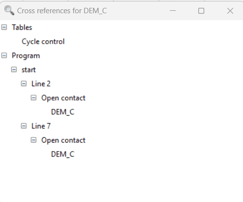
- Cross-references: click this option to display a popup window showing all the places where a specific variable is used. For example, the screenshot below shows the cross-references for the variable DEM_C (it is used twice in the program: in the page “start” in line 2 and line 7).
5.5.1.1.4 COMMUNICATION (ALT+C)
This drop-down menu is similar to the “Communication” drop-down menu on the main menu bar of MicroLADDER.
Information
This tab is identical to the one found on the main window in the menu bar.
This drop-down menu will not be accessible from a function block but only from a PLC program.
- Connect: this option is available when no connection has yet been established. A popup window ‘Connect to MicroDRIVER’ will appear when this option is clicked on. Several fields (communication method, slave number and MicroDRIVER address) must be filled in to connect to the controller. You can also access the “Connection to MicroDRIVER” window using the “Connect” button in the Tools menu. For further information on how to establish a connection, refer to section 5.3.2 Establishing a connection.

- Disconnect: this option is available when a connection has already been established. By clicking on this function the communication with the PLC will be stopped.
- Read slave number: this option is only available when a connection to a PLC has been established. It is used to obtain the slave number of a specific slave, when it is planned to connect several of them in series on the same line.
- Write slave number: this option is only available when one (and only one) connection with a PLC has been established. It allows to modify its slave number.
- Program start: this option starts a program when the PLC is in the STOP state. A popup window appears indicating that the program has started.
- Program stop: this function stops a program when the PLC is in the RUN state.
- Reset equipment: this option resets the PLC to its BOOT state. It is useful to test its reactions when it is switched on and off for example.
- Reset variables: this function resets all variables to their initial values and does not stop the program. The PLC is always in the RUN state. It is useful to simulate a behavior.
- Loading a program: this option opens a popup window “Loading a program” allowing us to choose the hexadecimal file (.hex) that we want to load on the PLC. This action takes several tens of seconds, so it is faster to load using an SD card if the PLC has an SD card reader.
Information:
It is possible to know the corresponding key associated with the Alt+key shortcuts for direct access to each drop-down menu in the menu bar by clicking Alt while the menu bar is active or visible. The letters associated with each key will appear underlined.
5.5.1.2 Toolbar of the variable editor
The Variable Editor toolbar appears at the top of the Variable Editor window. It includes the following items:

The following items are included in the Variable Editor toolbar:

User variables/System variables/Created user tables: select the type of variables you want to display from the drop-down list: system variables, user variables or one of the tables you may have created.

Add: click on this option to include a new variable in the current MicroLADDER project. Give this new variable a name (either an address or a mnemonic) and define its properties in the new properties popup window that appears (see section 5.5.1.3 Variable properties)

Remove: this option removes a variable from a table, but not from the project.

Delete: select a variable (or variables by selecting them with Ctrl or Shift) and then click on it to delete it/them. Variables cannot be deleted when they are used in the program.

Connect: Click this option to connect to a PLC when it is disconnected or to disconnect it when it is connected. When connecting, a new window will appear by clicking on this option. You are then asked to set the appropriate parameters for the communication method, the slave number and the address of the MicroDRIVER in order to connect to the PLC. To disconnect, simply click on this option as long as the connection with the PLC is active. The window for connection to MicroDRIVER can also be accessed from the “Communication” tab on the menu bar of the variable editor.

Search: use this search bar to search for a specific variable either by its address (such as “%S1”) or by its mnemonic. The search is not case sensitive. You have to make sure that you are in the right type of variable (if you search for a cycle control variable and you have selected user variables, the search will not return any result)
5.5.1.3 Variable properties
The following information is displayed when a variable is created or modified. To access it, double-click on the variable or right-click and select “Properties”.
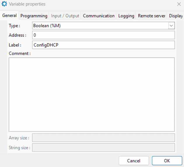
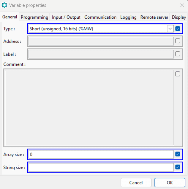
5.5.1.3.1 General tab
- Type: type of variable. To better understand the prefixes used for the address of the variables, see section 6.2 Data types.
- Address: memory address of the variable in the PLC. For a better understanding of the prefixes used for the address of variables, see section 6.2 Data types.
- Label: name given to the variable.
- Comment: brief explanation of the variable.
- Array size : in case of an array, number of elements allocated in the array. If the variable is not an array, this box will be grayed out.
- String size : in the case of a string, maximum number of characters in the string. If the variable is not a string, this box will be grayed out.

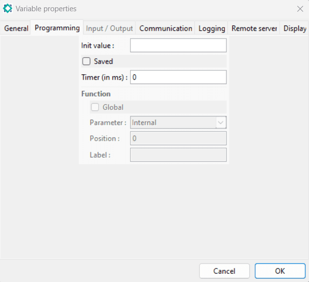
5.5.1.3.2 Programming tab
- Initial value : value loaded on the variable at the start of the application or during an initialization request.
- Saved: If the PLC has a saved memory, you can select this option and the value will be kept during the power interruption. The user can determine when the EEPROM is saved.
- Timer (in ms) : period of time after which the variable is decremented by 1.
In addition to these features, if the program is a function block then these fields can be filled in:
- Global: this property can be used with functions. It allows the variable to keep its value between two calls.
- Parameter: used to declare variables in a function block. See section 5.8 Creating a function block for more information.
- Position : allows to define the order of the inputs/outputs in a function.
- Label : allows to give a name to a variable when it appears in a function.
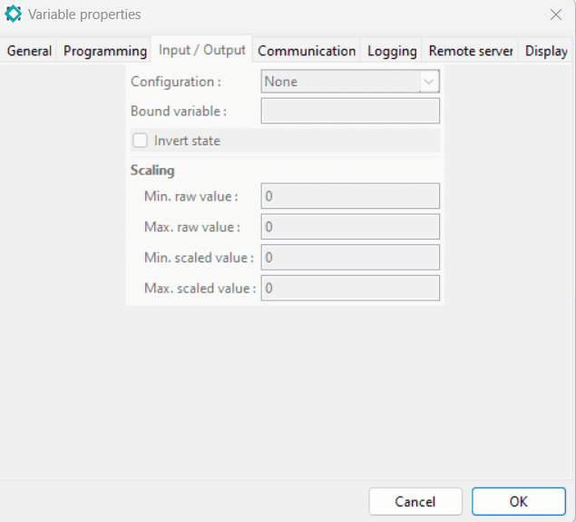
5.5.1.3.3 Input/Output tab
This tab is not available for function block programs.
- Configuration: parameterization of the analog inputs
- Associated variable : only for input/output variables that correspond to connected elements. This feature associates a user variable with a hardware variable.
- Invert state : available only when using a boolean linked variable. This feature allows to invert the state between the local variable and the remote variable.
Scaling is only available when using a non-boolean linked variable. It is possible to scale values by specifying a raw value scale and associating a scaled value range to it.
- Min. raw value : minimum raw value for the analog input
- Max. raw value : maximum raw value for the analog input
- Min. scaled value : minimum scaled value for the linked variable
- Max. scaled value : maximum scaled value for the linked variable
An example is that if we have a sensor returning data between 0 and 20000 (for 0-20mA) then these values refer to temperatures between -20°C and +80°C (0 representing -20°C and 20000 representing 80°C). In the field “Associated variable” associate a linked variable of type %MF.
To set up the scaling, fill in the field “Min. gross value” with 0, the field “Max. gross value” with 20000, the field “Min. scaled value” with -20 and the field “Max. scaled value” with 80.
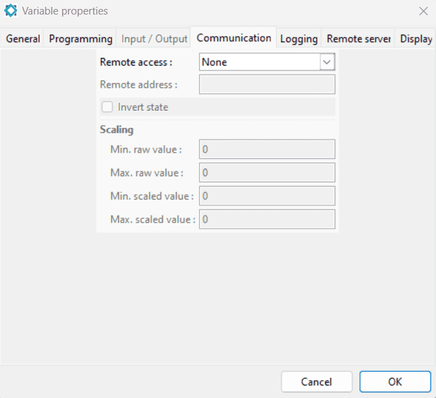
5.5.1.3.4 Communication Tab
- Remote access:
– “None” : no communication for this variable
– “Read only”: the communication cycle is a periodic read frame. The variable in the PLC is a copy of the variable in the remote equipment.
– “Write only”: the communication cycle is a periodic read frame. The variable in the remote equipment is a copy of the variable in the PLC.
– “Read / Write”: the communication cycle is a periodic read frame and a write frame when necessary. Each time the variable changes in the PLC, the value is written to the remote device. Each time the variable changes in the remote device, the value is updated in the PLC. - Remote address: address of the tag in the remote device. The address must specify the name of the variable followed by a dot and the number of the equipment. For example “%MW2.3” is a %MW variable at address 2 of remote device number 3.
- Invert state : available only when using a boolean linked variable. This feature allows to invert the state between the local variable and the remote variable.
It is possible to scale values, and to do this, specify a raw value scale and associate a scaled value range with it.
- Min. raw value : minimum raw value in the remote device
- Max. raw value : maximum raw value in the remote device
- Min. scaled value : minimum scaled value in the PLC
- Max. scaled value : maximum scaled value in the PLC
For example, if there are data between 0 and 100 in the remote device and you want these values to be between 0 and 10 in the PLC, then you must fill the “Min. raw value” field with 0, the “Max. raw value” field with 100, the “Min. scaled value” field with 0 and the “Max. scaled value” field with 10.
Thus, for example, when the value is 233 in the remote equipment, the value is 23.3 in the PLC and vice versa.
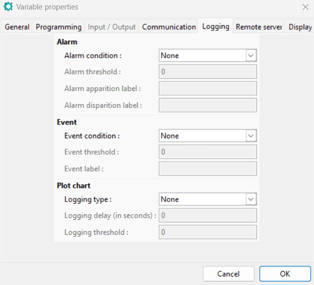
5.5.1.3.5 LOGGING TAB
- Alarm condition: drop-down menu allowing you to choose the logical operator for the alarm condition (<, <=, >, >=, != and ==). If you choose “None” then there will be no alarms for this variable.
- Alarm threshold: value of the condition with which the alarm is activated. An alarm is a condition, and an event occurs and is created whenever a threshold is exceeded.
- Alarm apparition label: text that will appear when the alarm condition is present.
- Alarm disparition label: text that will appear when the alarm condition disappears.
- Event condition: drop-down menu allowing you to choose the logical operator for the event condition (<, <=, >, >=, != and ==). If you choose “None” then there will be no events for this variable.
- Event threshold: value of the condition with which an event will be activated.
- Event label: text that will appear when the event is present.
- Logging type: drop-down menu allowing you to choose how you want to archive the value curves over time. There are three types of historization :
– “None”: no history made.
– “Standard” : takes a value with a regular interval
– “Averaged”: takes an average value over a given period of time - Logging delay (in seconds): archiving time. It depends on the type of logging among two possible ones:
– “Standard” : specified time (1 minute for example)
– “Averaged”: specified period of time - Logging threshold: threshold beyond which the value will be recorded.
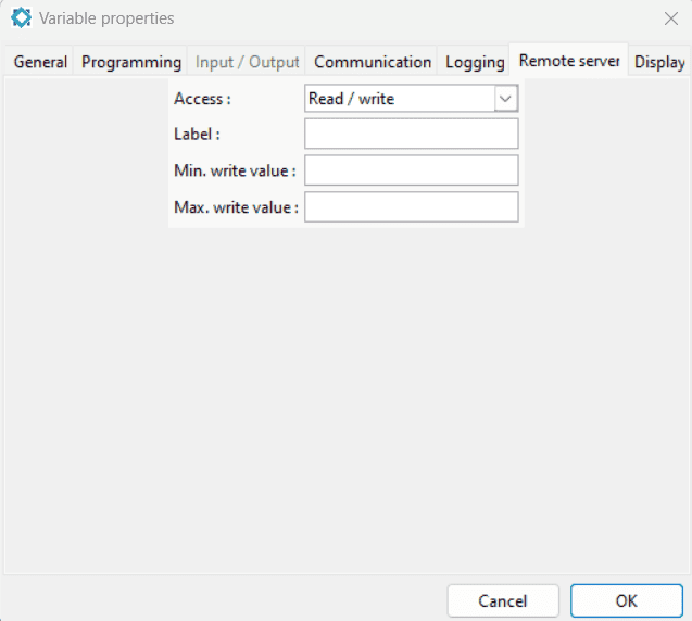
5.5.1.3.6 Remote Server Tab
- Label: text that will be displayed in the “Label” field on MicroSERVER for this variable
- Min. write value: minimum value that the variable can have when you want to force it
- Max. write value: maximum value that the variable can have when you want to force it
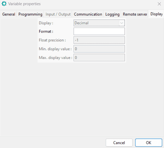
5.5.1.3.7 Display tab
These parameters are used in the graphic interface (MicroHMI), in the server (MicroSERVER) and in the display of the formatted value in MicroLADDER. The various fields are available below:
- Representation: drop-down menu allowing to select how the value of the variable will be represented among:
– decimal
– binary
– hexadecimal - Format: format of the displayed value. The value of the variable is represented by “%v”. For example, if you write “%v°C” then the value of the variable will be displayed followed by the unit “°C”.
- Precision: number indicating the number of digits after the decimal point of a decimal number. -1 means no limit i.e. all digits after the decimal point.
- Min. display value : Minimum value to be displayed of a variable for the synoptic displays, gauges, etc. in MicroHMI.
- Max. display value : Maximum value to be displayed of a variable for synoptic displays, gauges, etc. in MicroHMI.
5.5.2 Variables Type
The variables considered in a MicroLADDER program can be divided into two categories:
– system variables
– user variables
5.5.2.1 System variables
System variables are inherent to the PLC. Their properties cannot be modified so the variable editor will only display their value in real time.
These variables can be classified in twelve tables:
- System information :%SW13, %SW14, %SW23, %SW24
- Cycle control : %S0, %S1, %S16
- watchdog : %S15, %S20 à %S22, %SW0 à %SW2, %SW4
- Time stamp : %S5 à %S8, %S24, %SW5 à %SW12
- Variable management : %S2, %S18, %SW15 à %SW22
- Interruption : %SW25
- Serial ports : %SW34 à %SW81
- Ethernet : %S25, %SW96 à %SW137, %SW225 à %SW262
- WiFi : %S26, %SW91 à %SW95,%SW138 à %SW175, %SW189
- Radio :%SW190 à %SW191, %SW200 à %SW211
- Bluetooth : %SW214 à %SW229
- Input / output management : %S11, %S12, %SW26
5.5.2.2 User variables
The user may need additional variables in a program. If no variables have yet been created by the user then no variables will be displayed in the user variables in the variable editor. Variables already created in the program (in Ladder or C) are created by the MicroLADDER software and will therefore be displayed in the variable editor. However, a manual entry is necessary to define the properties of the variable.
5.5.2.3 Creating variables
5.5.2.3.1 Creating variables automatically
It is possible to create variables automatically in a Ladder or C program. To do so, you just have to write the type of the variable followed by the address. For example, if you want to create a variable of type unsigned integer on 16 bits at address 1, then you write %MW1. This will automatically generate the variable in the table of variables.
Warning
This way of creating variables is fast but you can quickly get lost when you have several different variables and to remember the use of each variable.
5.5.2.3.2 Creating variables manually
To create variables with more precise characteristics than their type+address then we will create variables manually from the variable editor.

To create variables manually, click on the “Add” icon, choose the type and then give a mnemonic to the variable and determine its properties (see section 5.5.1.3 Variable properties) in the new popup window that appears.
Warning
When writing a mnemonic, it is not necessary to define an address. The variable will then be stored in a free space of the memory area of variables of the same type. However, this approach is not recommended because it is not known at which addresses the variables will be stored.
5.5.2.4 Variable identification
The variable is identified by the combination of type+address.
For example, if the type is boolean and the address is 10. The variable is identified as %M10.
Several types of variables common to function blocks and PLC programs are available among :
- boolean
- 16-bit unsigned integer
- 32-bit signed integer
- 32-bit signed float
- character string
If the program is not a function block, these variables are available additionally:
- digital inputs
- analog inputs
- digital outputs
- analog outputs
The address is the offset of the variable in the memory of the PLC. The address must be unique for each variable of the same type. For example, it is not allowed to define two variables %M0 but one variable %M0 and another %MW0 are allowed. The definition of an address is not mandatory. In this case, a compilation will locate the variable in a free space of the variable area of the same type.
It is necessary if a variable must be sent to a server or if the PLC must be configured as a Modbus slave, to have another equipment read/write this variable.
Variables can be used in a MicroLADDER program by calling them by their address or mnemonic.
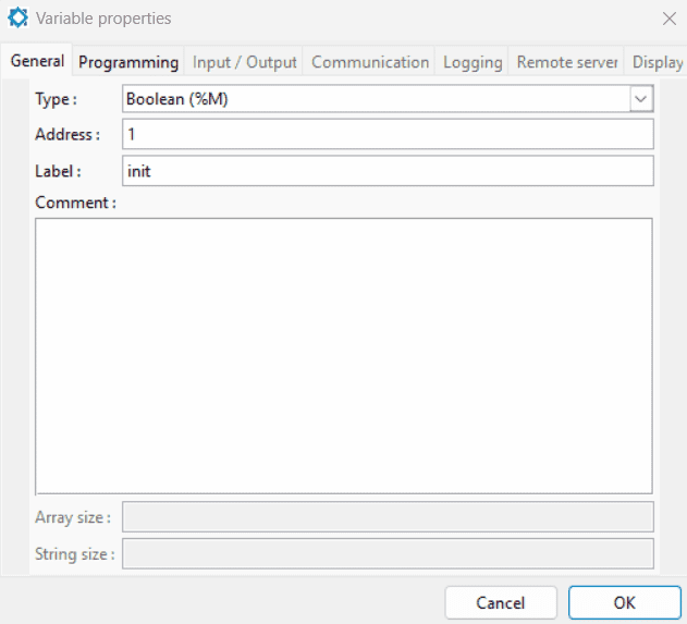
For example, in our program, if we want to use this variable, we can write either %M1 or init. Both entries will give the same result. For example, these two lines set the variable to 0:
%M1 = 0;
Init = 0;
5.5.3 Exporting/Importing variables
5.5.3.1 Exporting variables
The variable list can be exported to a CSV file and imported from a CSV file for use in other programs.
To export variables, go to the “Tables” tab and then “Export variables from this table”. A popup window opens asking us to specify the structure of the CSV file. It is better not to change the default structure to avoid possible import problems. If you change it when exporting, make sure to respect the same order when importing the variables. Then click on “OK”.

5.5.3.2 Modifying the table of variables in a CSV file
Once the list of variables has been exported in CSV format, it is possible to modify this table by opening the file (with Excel or LibreOffice Calc). This approach is useful especially when you want to create a large table. We create our table then the variable corresponding to the first cell of the table. After the export of the variables, we open the CSV file then we just have to copy and paste the variable of the first cell of the table and change each time the address to create the variables of the other cells of the table. In this way we keep the same attributes for all the cells (for more information on tables refer to section 6.2.11 Tables)
5.5.3.3 Importing variables
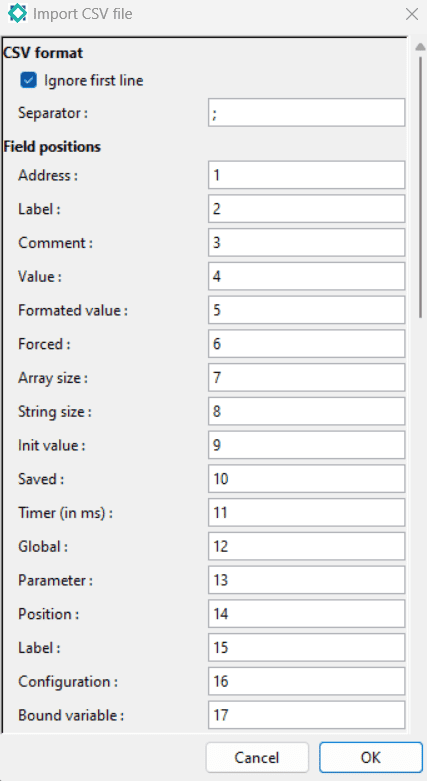
To import variables into a program, go to the “Tables” tab and then to “Import variables into this table”. A popup window allowing you to select the CSV file will open. Once the file is selected, click on “Validate” a new window named “Import a CSV file” opens. There is no need to change anything in this window. Finally, click again on “Validate”.
The import of variables is done by overwriting the current variables, so make sure that you do not have in your current project a variable with the same address or mnemonic, because it will be directly replaced.
5.5.4 Variable multi-edition
It is possible to modify the properties of several variables together instead of modifying each variable separately.
To do this, follow the steps below:
- Select the variables with Ctrl or Shift.
- Then click on the “Variables” tab and then on “Properties” or right-click from the variable editor window and click on “Properties”.
- A “Variable Properties” popup window opens. Properties that have the same value on all variables appear selected and framed in blue while properties that have a different value appear unselected and grey.
- Select the fields you want to change and set the new value. All selected properties will be applied to all variables. Unselected properties will remain unchanged.
- Confirm your changes by clicking on “OK”. Otherwise click on “Cancel” or close the window.
Warning
It is important not to modify the properties of variables that must be unique such as the mnemonic or the address and type.
5.6 Objects available in Ladder language
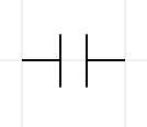
5.6.1 Open contact
It is activated when the value of the represented variable (input, internal variable or system bit) is equal to 1. It is deactivated when its value is equal to 0. It can be used either with a binary variable, or as a comparison of the type %MW0>0 with integer, long or floating-point variables. This means that each variable value different from 0 will activate the contact.
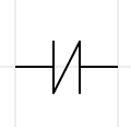
5.6.2 Closed contact
It is activated when the value of the variable represented (input, internal variable or system bit) is 0. It is deactivated when its value is 1. The same remarks can be made as those already made for the open contact.
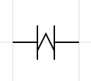
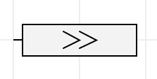
5.6.3 Rising edge
It is activated when there is a change in the value of the represented variable (input, internal variable or system bit) from 0 to 1.
Each edge is managed by an internal variable (of size 1 byte) independent of the internal variable used. The edge is valid for exactly one complete cycle. If the variable changes after the edge then during the next cycle the edge will easily detect it.
There is potentially a bug with indexed bits, if the index has changed from one cycle to the next.
Complex expressions and word bits can be handled.
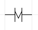
5.6.4 Falling edge
It is activated when there is a change in the value of the variable represented (input, internal variable or system bit) from 1 to 0.
The same remarks can be made as for the rising edge.
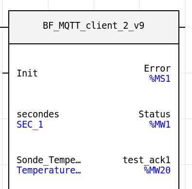
5.6.5 Function
When a function is imported into the current program, it can be inserted as a ladder instruction. All you have to do is define the input variables and connect the outputs correctly.
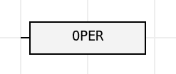
5.6.6 Operate
This block will allow to define operations between variables.
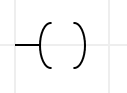
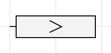
5.6.7 On
It is activated when the left combination gives a result of 1.
Its activation means that it will return a logical value of 1.
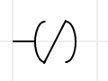
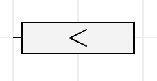
5.6.8 Off
It is activated when the left combination gives a result of 0.
Its activation means that it will return a logical value of 0.
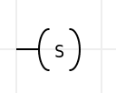
5.6.9 Set
This element will force the associated variable to 1. The variable can only be set to 0 with a “Reset”.
It is usually used for bit storage.
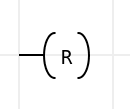
5.6.10 Reset
This element will set the associated variable to 0.
It deactivates a variable previously activated with a “Set”.
5.6.11 Call
This block calls a page of the program and executes its code. Once the code is executed, the main program resumes at the next line where the call was made.
5.6.12 Jump
This block allows you to advance by skipping a certain number of instructions.
5.6.13 Return
This block allows you to go backwards by skipping a certain number of instructions.

5.6.14 Marker
This block is used by the last two instructions to materialize the place where the Goto or the Return stops in the program.

5.6.15 Comment
This block allows you to add a comment block in the program.
5.6.16 Insert an empty line
This command allows you to add empty lines to make space in the program.
5.6.17 Delete empty lines
This command will remove the empty lines
5.6.18 Paste
This command allows you to paste an element that you have previously copied.
5.6.19 Connecting elements
To connect elements to each other, simply double-click on a line in the gray background grid of a program where a connection is to be made or click and drag from one element to another (or to a line).
5.6.20 Disconnecting elements
To disconnect items from each other, right-click on the connector and select “Disconnect” or double-click on the connection you wish to remove.
5.7 Create a program
To better understand how MicroLADDER works, some examples of programs are presented below:
5.7.1 Create a first simple program in LADDER
In order to have a first approach, we are going to program a PLC to execute a simple task.
Our system will be composed of:
- a MicroArm-A1 controller
- the display of the MicroArm-A1 controller whose LED backlight is an input at address %Q0
- a push button: digital input at address %I100
- one LED: digital output at address %Q100
Information
The values of these addresses are not given randomly but are indicated in the technical documentation of the PLC.
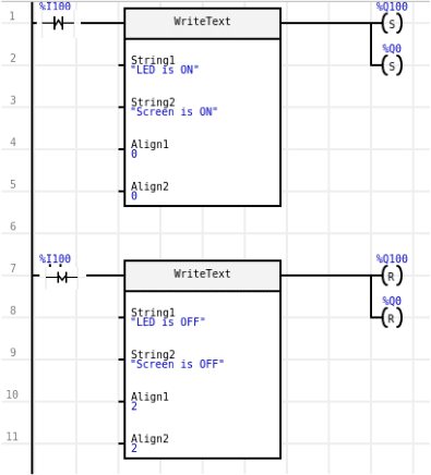
Our program will have to meet the specifications:
- The LED will only be lit when the push button is pressed. Otherwise, it will remain off.
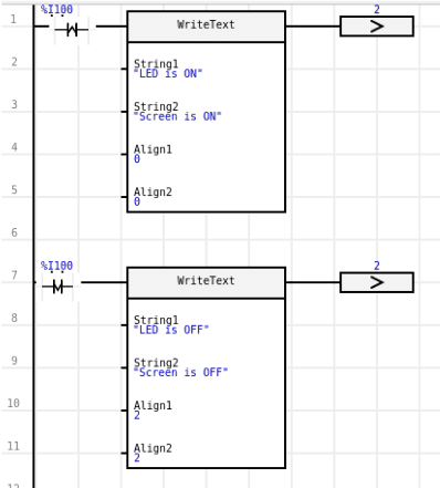
- When the LED is lit (meaning that the push button is pushed), the MicroARM-A1 display also has the backlight on and the text displayed is as follows:
– First line: “LED is on” positioned on the left side of the screen
– Second line: “Screen is on” positioned on the left side of the screen - When the LED is off (meaning that the push button is released), the MicroARM-A1 display has the backlight off and the text displayed is as follows:
– First line: “LED is OFF” positioned on the right side of the screen
– Second line: “The screen is off” positioned on the right side of the screen
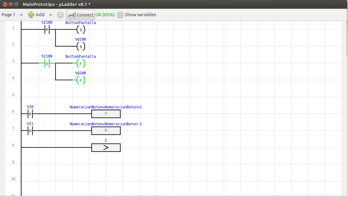
To write this program, the WriteText function is used. The following screenshot shows this program already implemented in the MicroLADDER.
| Interprétation | Interprétation Digitale | Ladder |
| Quand on pousse le bouton… | %I100 change de 0 à 1 | Front montant |
| Quand on éteint le bouton… | %I100 change de 1 à 0 | Front descendant |
| …LED ou écran à ON | %Q100 ou %Q0 est mis à 1 | Set |
| …LED ou écran à OFF | %Q100 ou %Q0 est à mis 0 | Reset |
5.7.2 Create a first simple program in C
We will create the same program as before (same system and same specifications) but the code will be C.
if (%I100 == 1)
{
  %Q100=1;
  %Q0=1;
  WriteText(“LED is ON”,”Screen is ON”,0,0);
}
else
{
  %Q100=0;
  %Q0=0;
  WriteText(“LED is OFF”,”Screen is OFF”,2,2);
}
5.7.3 Create a first simple program combining Ladder and C
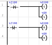
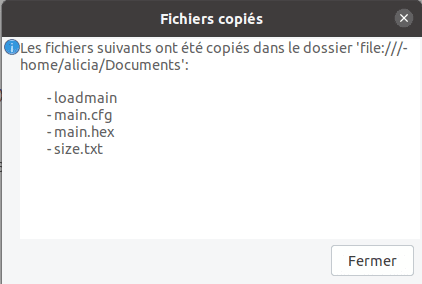
As mentioned in the previous sections, it is also possible to combine a program containing both Ladder and C code by structuring it in different pages. The same program as explained above is divided into two pages as follows:
- The first page contains the program that displays the text on the screen when the push button is pressed.
- A second page contains the program that activates the LED and the backlight of the LED display.
This can be done in two ways:
– First method: the main program is written in Ladder and calls a C page.
– Second method: the main program is written in C code and it calls a Ladder page.
5.7.3.1 First method
Contents of page 1:
Contents of page 2:
if (%I100==1)
{
  %Q100=1;
  %Q0=1;
}
else
{
  %Q100=0;
  %Q0=0;
}
5.7.3.2 Second method
Contents of page 1:
if (%I100 == 1)
{
  WriteText("LED is ON","Screen is ON", 0,0);
  page_2();
}
else
{
  WriteText("LED
  page_2();
}
Contents of page 2:
5.7.4 Compile and load a program on the PLC
After creating the program, it must be compiled before loading it into the PLC.
It is advisable to save the project before compiling it by clicking on the “File” tab then on “Save” in the menu bar.
We can then compile the program by clicking on the tab “Program” then on “Compile” always in the menu bar. A popup window appears, asking us to specify the place where we want to save these new files:
- If the PLC is equipped with an SD card reader and you wish to load the program via this method, then you copy the files directly onto the SD card. The program will be automatically loaded when the SD card is inserted in the PLC.
- If you do not wish to load the program with the SD card or if the PLC does not allow this option, simply select a folder on the computer. It is possible to load the hexadecimal file (.hex) on the PC via MicroLADDER or the MicroCONTROL program.
If the compilation is successful, the files main.hex, main.cfg, loadmain and size.txt will have been created and a single new window “Files copied” will appear to confirm that the compilation was successful.
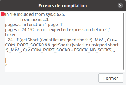
If there are errors in the program, a “Compilation errors” popup window will appear as well as a second popup window containing all the files and folders needed for compilation. These are the system code files and folders. As long as there are errors in the program, it will not compile and these two windows will open.
5.8 Create a function block
In MicroLADDER, a function can be created in two different ways:
- In the same program as the application that calls it. In this case, the function will just be called like in other languages
- In a “Function block” program. In this case, it will have to be imported before an application can use it. This can be useful to manage identical sub-parts in a program or in several programs. To declare a function in a function block, click on the “Program” tab then select “Program type” then “Function block”.
A function can also call other functions.
In this part, we will focus on the creation of functions in a function block.
5.8.1 Definition of variables
It was explained earlier that variables can be declared automatically. It is always possible to do this in a function block but it is necessary to manually define the input and output variables of the created function.
If you choose to code a function in a “Function block” then four different types of variables can be declared. To choose the type of a variable, go to the variable editor then go to the “Variable properties” then to the “Programming” tab. The type of the variable is to be selected in the drop-down menu “Parameter”:
- internal: the variable is only valid inside the function. It is initialized at each function call, except in the case where the “Global” property is selected.
- input: the value given by the calling application is sent when the function is called. The value will be visible in the function block on the Ladder page.
- output: the value is returned to the calling application at the end of the function execution. The value will be visible in the function block on the Ladder page.
- external: when the function is called, the variable takes the value given by the calling application. At the end of the execution of the function, the value is returned to the calling application. It does not appear in the Ladder object of the function on a Ladder page.
5.8.2 Using a function block
The function block must be imported into the application by clicking on the “Library” tab and then on “Import a function”. A window opens allowing you to select the file of the desired function block.
A single import is sufficient, even if the function is used several times.
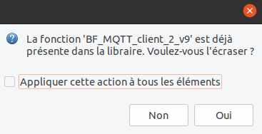
However, every time we make a change in the function block, we have to import the function block again. After selecting the function block file, a popup window will open. Click “Yes” to overwrite the existing function block, otherwise click “No”.
5.8.2.1 Import a function
A “Function” object must be imported into a program page by clicking on the “Library” tab and then on “Import a function”.
For binary data, the contacts and coils can be connected to the function’s connections. For numerical data, you must double-click on the function and define the variables exchanged. This last method can also be used for binary data.
Information
A function cannot access the bits of the system words (%S and %SW). They must be accessed as parameters.
Each time a function is used, it organizes its own memory space. This allows the same function to be used several times in a program and to save data in memory at each call, from the current cycle to the next.
5.8.2.2 Using a function in Ladder
In Ladder, to use a function that we have imported, we must insert a “Function” object, by right-clicking on the page and selecting “Function”. A drop-down menu will then ask us which function we want to import. Click on the one you want to use.
Now it is necessary to declare the input and output data (if there are any). Binary input data, contacts and coils can be linked to the function. For numerical data, double-click on the function and define the variables exchanged. This last method can also be used for binary data.
5.8.2.3 Using a function in C
In C, the function must be called by its name and the variables must be introduced as parameters in the order in which they were declared: first the input variables, then the output variables and finally the external variables. This approach is similar to calling a function in the classical C language, with the output and external variables added.
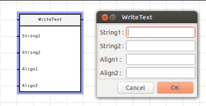
string1=”Good morning”;
string2=”Good night”;
align1=1;
align2=1;
WriteText (string1, string2, align1, align2);
5.9 Create global functions and variables
If on a page, we want to use functions or variables declared and defined on another C page then there is a manipulation to be done before we can use them.
Indeed, on the C page that contains the global functions and variables, these must be enclosed in global tags in this way:
<global>

(declaration of variables and/or declaration and/or definition of function)

</global>
5.10 Using timers
5.10.1 What is a timer?
A timer has one of the following statuses:
- timeout: when the timeout value is equal to zero.
- active timer: when the value of the timer is greater than zero and less than the value of its countdown period. In this case its value decreases with the countdown period indicated in the variable.
5.10.2 Better understanding of timers
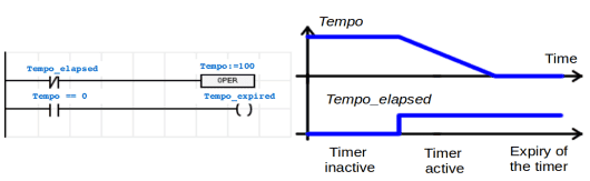
In the first state, there is no elapsed time (the binary variable Tempo_elapsed is 0), the value of the countdown period (100) is loaded into the variable Tempo. The state of the timer is inactive. As long as Tempo_elapsed is 0, the Tempo variable remains at 100, so no countdown is performed.
In the second state, the binary variable Tempo_elapsed is set to 1. The value of the countdown period (100) is no longer written to the Tempo variable and the value of Tempo decreases. The timer state is active.
In the third state, the Tempo value drops to 0 after the countdown. The timer has expired and is again inactive.
5.10.3 How to use a timer?
To use a timer, the “Timer(in ms)” property of a variable must be set. Go to the variable editor then double click on the variable on which you want to put a timer. A popup window opens and go to the “Programming” tab then fill in the “Initial value” fields with the value of the timer. In the field “Timer (in ms)”, write the decrement step. If we want our timer to be decremented every 1 s, then write 1000 in this field.
The countdown period (in ms) in the “Timer (in ms)” field and the timer value will be handled by the system as a timer.
The use of a ladder or C delay is similar for both cases.
5.10.3.1 Example of the use of a timer
To better understand how to use a timer we use the following example:
Looking again at the MicroARM-A1 controller, we will use the program described in section 5.7 Create a program to add new functions to it:
– By pressing the button (%I0), a counter is activated. This counter counts only the time during which it is pushed.
– Releasing the button resets the counter to zero.
– After three seconds of pressing the button, the LCD backlight turns on if it was off, or turns off if it was on.
This program can be created in Ladder as shown in the following screenshot:
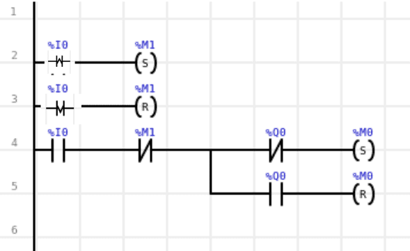
A new boolean variable (%M1) indicating whether the button is pressed (1) or not (0) has been added. To set the timer, write three in the “Initial value” field and 1000 in “Timer (in ms)” so that the counter is decremented every second.
6. Software environment
6.1 System architecture
6.1.1 Monitor
The monitor is the basic software layer. It is then used to load the software application. The user will not need to modify it, unless a new software download may require reloading the monitor software.
If an SD card is available at power-up, the FORCE_MON and RUN parameters of the “MAIN.CFG” file available on the SD card will determine the launch of the main loop and the application.
The parameters are saved at the same time on the SD card and on the EEPROM. It is therefore possible to operate without the SD card. The monitor is loaded by Sirea.
6.1.1.1 To know the operating status of the PLC thanks to an LED
Each PLC has a LED that can be soldered on the board or accessed through a connector. The operating mode of the PLC can be determined by the way the LED flashes.
6.1.1.1.1 Monitoring mode
The LED flashes slowly: 500 ms on / 500 ms off. The PLC is under Modbus control. It can be controlled by MicroCONTROL.
6.1.1.1.2 Transfer of the program from the SD card to the PLC memory
The LED flashes rapidly: 100 ms on/ 100 ms off.
The transfer only takes a few seconds. It occurs when MicroCONTROL has been transferred. It can be transferred by pressing the button or by passing the parameter on the SD card.
6.1.1.1.3 STOP mode
The LED flashes slowly and remains mainly off: 100 ms on/ 900 ms off.
The PLC is no longer on the monitor, the main loop starts, the application does not run. Our PLC is stopped.
6.1.1.1.4 RUN mode
The LED flashes slowly and remains mainly lit: 900 ms on/ 100 ms off. The application runs.
Our PLC is now in operation.
6.1.1.1.5 Incompatible versions between the monitor and the application
The LED lights up in static red. This only happens when the application starts and the data structures registered by the monitor are different from the data structures registered by the application. This can create problems with the registered variables.
6.1.2 main.cfg file
This file is located on the SD card. It contains the settings. It is read and rewritten when the application is launched or when the SD card is inserted.
Therefore, if the file is modified, it is completely rewritten. If changes are to be made to this file, it is important to proceed with caution.
Some characteristics of this file can be modified by variables if necessary.
| Variables of the main.cfg file | Description |
| FORCE_MON | If it is at 1, it imposes to stay on the monitor and not to launch the application |
| LOAD | If it is 1, it indicates that the program must be loaded into memory. It is then reset to 0 at the end of the loading |
| FIRST_RUN | If it is set to 1, it indicates that the variables must be initialized. It is not necessary to set it to 1 when loading the application because the system does it by itself. This is the %S2 variable |
| RUN | If it is 1, it allows to switch from the application in STOP to the application in RUN |
| RESET_SW | If it is 1, it indicates that the cycle time has been exceeded (watchdog) and blocks the PLC on the main loop. It is the variable %S21 |
| RESET_CFG | If it is 1, it resets the variables in the “main.cfg” file |
| LOAD_IO_CFG | If it is 1, it allows to reload the “var.csv” file and to reinitialize the history of curves, alarms and events. It is the variable %S19 |
| MODE_DST | If it is set to 1, it is used to memorize the daylight saving time management. This is the variable %SW11 |
| TIME_OFF | Allows you to set the offset from UTC time in minutes. It is useful for automatic time setting. It is the %SW12 variable |
| BOOT_VER | Indicates the version of the boot installed on the PLC. This is the %SW23 variable |
| W_SSID | Allows you to set the SSID (access point name) for Wi-Fi. The standard allows up to 32 characters |
| W_STYPE | Allows you to set the type of encryption for Wi-Fi. Possible values are “” (empty string uses automatic detection), OPEN (no encryption), WEP, WPA, WPAAES, WPA2AES, WPA2TKIP, WPA2 |
| W_SKEY | Allows you to set the security key for Wi-Fi |
The following example is the code of a main.cfg file with default values. The PLC will start the main loop of the application present in the memory. If there is no application, the system will be blocked.
FORCE_MON=0
LOAD=0
RUN=0
6.1.3 Loadmain file
When this file is present on the SD card, the application is reloaded and the file is deleted.
This method is equivalent to setting the LOAD variable to 1, but it avoids modifying the other variables in main.cfg. The content of the file is not important, only its presence counts. It is therefore possible to create a file called “loadmain” on the SD card. The PLC detects this file and loads the main.hex file in its memory. The fastest method is to let MicroLADDER save the compiled files directly to the SD card and then place the SD card in the controller.
6.1.4 Load a program
It is not mandatory to have an SD card. If you have one, it must be formatted in FAT32. Otherwise you can load a program via the network.
6.1.4.1 Via the network with MicroLADDER
The MicroLADDER program allows you to load hexadecimal files (.hex), i.e. already compiled files.
The transfer can be done through a serial port or through the Ethernet port. It is thus possible to load it remotely from the application code. To do this, go to the “Communication” tab and then click on “Loading a program”. A window will open allowing us to select the hexadecimal file to transfer.
The file is first transferred to the SD card, if an SD card is available. After the transfer process, the file will be loaded into the memory of the PLC. The application can then be started via MicroLADDER by going to the “Communication” tab and clicking on “Program start”.
When loading an application into the PLC for the first time, it is necessary to set FORCE_MON=1 in the MAIN.CFG file on the SD card. Otherwise, the PLC will try to launch the main loop of the application, even if it does not exist.
6.1.4.2 Via SD Card
If the PLC has an SD card, you can simply copy the file compiled by MicroLADDER (main.hex) to the SD card and create the file main.cfg which contains the following information
FORCE_MON=0
LOAD=1
RUN=1
The SD card must then be inserted into the PLC. The operating status LED indicates the transfer of the program from the SD card to the PLC memory by rapid flashing. Once the program has been transferred, the operating status LED indicates the execution of the application by flashing, mainly with the status LED on.
6.1.5 Saving variables
6.1.5.1 RAM Saved
Some PLCs have a saved RAM. You just have to check the option “Saved” in the properties of the variable and the system manages the backup autonomously.
6.1.5.2 EEPROM or FRAM
If the PLC does not have a saved RAM but an EEPROM or FRAM, it is possible to use the saved variables. When %S18 goes to 1, the system starts a backup of all the variables that have the “Saved” property checked.
With this version of MicroLADDER, you should no longer use the manual backup instructions. In fact, there is too much risk of using memory areas used by the system.
6.1.5.3 System words
The system words %SW15 to %SW22 are available to the user for saving words in the SD card. Saving is only done if there is a change in value. Saving can take place at the end of the Modbus communication with the programming console (if value forcing by the communication) and at the end of the PLC cycle (if value modification by the application).
Each saving takes from 180 to 200ms.
The reading of these words is carried out in a transparent way at the initialization.
There is a double backup on the SD card and in the EEPROM or FRAM.
6.2 Data types
It is important to note that MicroLADDER manages the API variables which can be used in Ladder objects, i.e. those which are accessible to real time monitoring by the software. However, in C pages, the internal variables declared may be of a different type from those proposed by MicroLADDER.
6.2.1 Digital inputs
A digital input is either 1 or 0. The prefix of a digital input is %I. An example is %I0. The data can be accessed in standard Modbus by making an offset (%I0 ⇒ %M20000).
The number of digital inputs varies depending on the PLC.
6.2.2 Analog inputs
The range of values and the number of values vary depending on the controller used. The prefix for an analog input is %IW. An example of an analog input is %IW100.
On some PLC, the analog inputs can be configured by jumpers. The “Configuration” property of the analog variables must then be tuned with MicroLADDER in order to have the correct value range and calibration.
| “Configuration” property | Analog input type |
| 0 | Default configuration. Corresponds to the configuration available on the PLC with the smallest configuration property value |
| 1 | 0-20mA. Value range generally 0-20000 points |
| 2 | 0-10V. Value range generally 0-10000 points |
| 3 | PT100. Temperature value usually in tenths of degrees Celsius |
The value ranges can be different depending on the PLC. These data are accessible in standard Modbus by making an offset (%IW0 ⇒ %MW40000).
6.2.3 Digital outputs
A digital output is either 1 or 0. The prefix of a digital output is %Q. An example is %Q0. The number of digital outputs varies depending on the controller.
The data can be accessed in standard Modbus by making an offset (%Q0 ⇒ %M21000).
6.2.4 Analog Outputs
The range of values and the number of values vary depending on the controller used. The prefix for an analog input is %QW. An example of an analog output is %QW0.
The data can be accessed in standard Modbus by shifting (%QW0 ⇒ %M41000).
6.2.5 PWM (Pulse Width Modulation) outputs
Not all PLCs have PWM (Pulse Width Modulation) outputs. For example, among the most widely used PLCs, MicroARM-12 and MicroARM-A2 have PWM outputs. For the MicroARM-12 controller, the two PWM outputs are %Q100 and %QW101. For the MicroARM-A2 PLC, the two outputs are %QW102 and %QW103. For further information, refer to the data sheet for each controller.
The variable %SW26 defines the frequency in Hz. This value must be between 0 and 65535 Hz (in practice the electronics do not allow a frequency higher than 10000 Hz).
A %QW variable per PWM output defines the duty cycle. This value must be between 0 and 1000. For example, to obtain a time slot at 1 of 20% and 0 of 80%, you must set %QW to 200. The PWM output signal varies between 0V and Vcc (power supply voltage).
To create a binary output, you must set %SW26 to 0 and write 0 or 1000 in the %QW variable to set the digital output to 0 or 1.
By default, %SW26 is 0 and %QW is 0, which corresponds to an output always at 0V.
When %SW26 is 0, the frequency is actually equal to the maximum frequency that the microcontroller of the PLC can go (this frequency is at least equal to 100000 Hz and can go up to 250000 Hz). This makes it possible to react more quickly to a change of state in binary mode because the current period necessarily ends before applying the new duty cycle.
Information
- It is possible to set a frequency up to 65535 Hz. However, if the frequency becomes too high, the signal becomes much worse (change of transistor state) or even unusable.
- The maximum limit is about 10 kHz depending on the load.
- To visualize the signal on the oscilloscope, a load resistor (about 1 kOhm) must be connected to the output terminals.
6.2.6 Bits
The value is either 0 or 1. A bit variable will have the prefix %M. An example of a bit is %M0.
The bits are character bits. Therefore, 8 bits use only 1 byte in memory. The access to a bit is longer than the access to a byte or a word
6.2.7 Integers
The value is between 0 and 65535. An integer variable will have the prefix %MW (Main Word). An example is %MW0.
6.2.8 Long
The value is between – 2 147 483 648 and 2 147 483 647. A long variable will have the prefix %MD. An example is %MD0.
The data can be accessed in standard Modbus by making an offset (%MD0 ⇒ %MW20020).
6.2.9 Float
The value is between 3.4 * 10^-38 and 3.4 * 10^38. A float variable will have the prefix %MF. An example is %MF0.
The data can be accessed in standard Modbus by doing an offset (%MF0 ⇒ %MW30020).
6.2.10 Character strings
The length of the string is indicated in the “Number of characters” field. A string variable will have a prefix %MS (Main String). An example of a variable is %MS0.
To access the nth character of the string %MS0, you must write %MS0[n-1]. For example, the 5th character of the array is accessed with MS0[4].
6.2.11 Arrays
We are often asked to create arrays of integers, floats, strings… . In this case, after having chosen the type of the variable (1st field of the tab “Variable properties”), you have to fill the field “Address” with the value constructed as follows: address[]. Then you have to fill the field “Number of elements” with the value of the size of the array. For example, in the screenshot below, we have created an array of 100 elements, the first element of which will be at address 100. To access the nth element, you must write %MW100[n-1]. For example, the 5th element is accessed with (%MW100)[4].
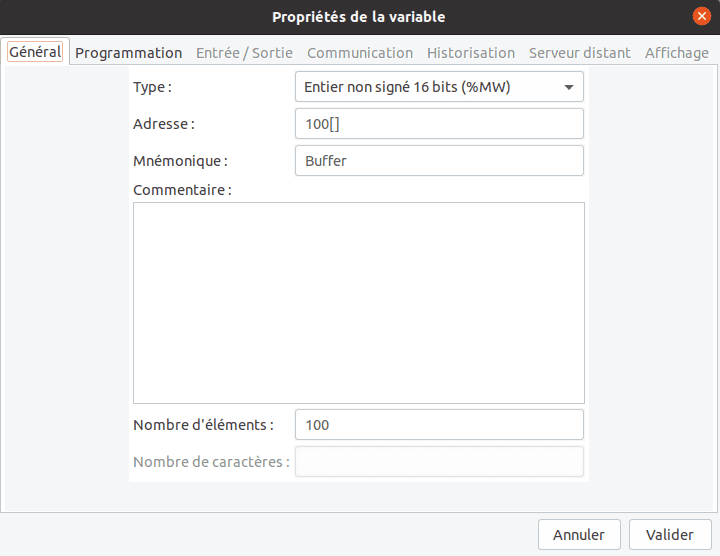
After validating our array, we have to create all the variables that make up the cells of our array. For example, if we have created an array of integers of 100 elements at the address %MW100, we will have to create 100 variables of integer type. In the following screenshot, we have created a first variable (1st cell of the array) at the address %MW100, a second variable (2nd cell of the array) at the address %MW101… .
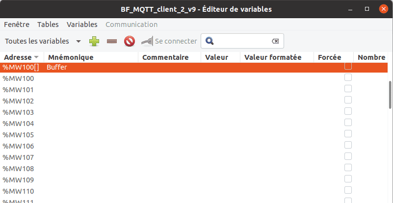
6.2.12 System bits
These data are accessible in standard Modbus by making an offset (%S0 ⇒ %M22000).
For the following, the term “program scanning” means that the PLC will execute the program sequentially.
| Bit | Mnémonique | Onglet | Description |
| %S0 | MST | Cycle control | Bit set to 1 on the first cycle of the system program that follows after a power-up or a program reload. Bit reset to 0 automatically after the first cycle is executed. This bit is slightly different from %S16 (DEM_C). |
| %S1 | RUN | Cycle control | Bit at 1, is set to state 0 by the user program or in data writing mode by the serial link (RUN/STOP command) Bit at 1 : program scanning. Bit at 0: program stop. |
| %S2 | INIT | Variable management | Bit at 0, is set to state 1 by the system at program start-up or in data writing mode via the serial link (INIT command). Bit at 1: loading of the initial values in the data values. No modification of the saved variables. Is automatically reset to 0 at the end of the initialization. |
| %S3 | Reserved | ||
| %S4 | Reserved | ||
| %S5 %S6 %S7 %S8 | MSEC_10 MSEC_100 SEC_1 MIN_1 | Time stamp | Bits whose change of state is clocked by the internal clock. They are asynchronous respecting the scanning cycle of the program. |
| %S9 | Reserved | ||
| %S10 | Reserved | ||
| %S11 | INIT_Q | Input/output management | Bit at 0, is set to 1 in the user program or by forcing it from the variable editor. Bit at 1 : causes the outputs to be set to 0. Bit at 0 : the outputs are updated by the user program. |
| %S12 | GEL_Q | Input/output management | Bit at 0, is set to state 1 in the user program or by forcing it from the variable editor. Bit at 1 : causes the outputs to be frozen in the state. Bit at 0 : the outputs are updated by the user program. |
| %S13 | MAJ_H | Bit at 0, is set to 1 in the user program or by forcing it from the variable editor. Bit at 1 : used to set the time and date : copy the values of the corresponding %SW5 to %SW10 in the system clock. Bit to 0 : the words %SW5 to %SW10 are refreshed by the system to indicate the current time and date. Since 29/06/12, this bit is no longer used and does not appear in the variable editor. It is possible to modify %SW5 to %SW10 at any time. The modification is taken at the end of the PLC cycle. | |
| %S15 | CDG | Watchdogs | Bit at 0, is set to 1 by the system as soon as the program cycle time exceeds the maximum cycle time defined in the system word SW1. It is automatically reset to 0 by an INIT command or at power-up (MST mode) or by the user program |
| %S16 | DEM_C | Cycle control | Bit set to 1 at the first user program scan, whatever the cause of the restart (powering up, reloading, start-up by the console). It is automatically reset to 0 at the end of the 1st cycle. This bit is slightly different from %S0 (MST). |
| %S17 | Reserved | ||
| %S18 | SAV_VARS | Variable management | Bit at 0, is set to state 1 in the user program or by forcing it from the variable editor. Causes a backup in the EEPROM or FRAM of the variables declared as saved. This bit is reset to 0 at the end of the backup. See section 6.1.5 Saving variables for more details. Be careful not to make a permanent backup because the EEPROM has a limited number of writes. |
| %S19 | LOAD_IO_CFG | Bit at 0, is set to state 1 in the user program or by forcing it from the variable editor. Causes the “var.csv” file to be reread and the alarm and event history to be reset. | |
| %S20 | RESET_HARD | Watchdogs | Unmanaged |
| %S21 | RESET_SOFT | Watchdogs | Bit at 0, is set to 1 by the system after a soft reset by the watchdog. This bit is reset to 0 when the program is restarted. See section 6.3 Watchdog for more details. |
| %S22 | RESET_ERR | Watchdogs | Unmanaged |
| %S23 | Reserved | ||
| %S24 | ALM_BAT_RTC | Time stamp | Normally set to 0, is set to 1 by the system when the backup battery battery is low |
| %S25 | DHCP | Ethernet | Use DHCP to set up the Ethernet port. Socket 3 is used for the initial request and for periodic requests. This means that DHCP temporarily takes over the socket at the expense of the application’s intended use. |
| %S26 | W_DHCP | Wifi | Use DHCP to set up the Wi-Fi port. Unlike Ethernet, the Wi-Fi module uses an internal socket that does not interfere with the application. |
| %S27 à %S49 | Reserved |
6.2.13 System words
These data are accessible in standard MODBUS by making an offset (%SW0 ⇒ %MW42000).
6.2.13.1 Modbus detail
| Bit | Mnemonic | Tab | Description |
| %SW0 | T_CYC | Watchdogs | PLC cycle time in ms. Accessible only in read mode. |
| %SW1 | S_CYC | Watchdogs | Monitoring of the PLC cycle time. Reference value allowing the system to control a polling time overrun (SW0 > SW1) and to set the %S15 bit (CDG). There is no stop of the application. Accessible in reading and writing. |
| %SW2 | Mx_CYC | Watchdogs | Timeout value of the PLC cycle time. Reference value allowing the system to control a maximum overrun of the polling time. In case of overrun (SW0 > SW2), the system saves the variables, forces the digital and analog outputs to 0 and switches the PLC to STOP mode. Bit %S21 (RESET_SOFT) is set to 1. Accessible in read and write mode. |
| %SW3 | Reserved | ||
| %SW4 | WD_HARD | Watchdogs | Unmanaged |
| %SW5 %SW6 %SW7 %SW8 %SW9 %SW10 | SECONDE MINUTE HEURE JOUR MOIS ANNEE | Time stamp | Date and time function. Words containing the current values of the date and time. Since 29/06/12, these words are accessible in reading and writing permanently, without taking into account the state of %S13 (MAJ_H). |
| %SW11 | MODE_DST | Time stamp | Automatic management of daylight saving time (valid since 16/07/12). • Value 0 : the system automatically manages the changeover to summer time according to European conventions. • Value 1: the system automatically manages the changeover to daylight saving time according to the American and Canadian conventions (valid since 02/02/21 and system code 14.10). • Value 2 to 65534 : reserved for future modes. • Value 65535 : no automatic management of daylight saving time. The hardware component (RTC) always remains in winter time. This is the value that can be used in the system words (%SW5 to %SW10) which takes into account the change to daylight saving time |
| %SW12 | TIME_OFF | Time stamp | Offset from UTC time (in minutes). For France, you have to put 60. |
| %SW13 | VERSION_SYS | System information | System code version. Read only. |
| %SW14 | VERSION_APP | System information | Application version. This word is available to the user to store the version number of his application. |
| %SW15 %SW16 %SW17 %SW18 %SW19 %SW20 %SW21 %SW22 | SAV1 SAV2 SAV3 SAV4 SAV5 SAV6 SAV7 SAV8 | Variable management | These 8 words are available for the user to save words. See section 6.1.5 Saving variables for more details. |
| %SW23 | VERSION_BOOT | System information | Boot version. Valid since the system code V8.0 of 26/07/16. |
| %SW24 | VERSION_MLADDER | System information | Version of MicroLADDER used for compilation. Valid since MicroLADDER V11.0 of 16/08/16. |
| %SW25 | FREQ_TIMER | Interruption | Period of call of the interruptive functions in µs. The functions that must be called must have the property “Call on interrupt” property validated. Value 0 : no call. Value different from 0 : call period in µs. This value is not saved. It must be initialized by the program. During the program, it can be modified at will. A value that is too low blocks the PLC. |
| %SW26 | FREQ_PWM | Input/output management | Frequency of the PWM output. |
%SW27 %SW28 %SW29 %SW30 %SW31 %SW32 | FET1 FET2 FET3 FET4 FET5 FET6 | Reading mask. It allows to prevent the refreshment of the inputs. Each input is associated with a bit. 1st and 2nd input bytes 3rd and 4th input byte 5th and 6th input byte 7th and 8th input byte 9th and 10th input byte 11th and 12th input byte Note: a 16-bit input card can straddle 2 system words. These variables no longer exist since MicroLADDER V16.0 of 14/03/19 and are no longer visible in the variable editor. It is now possible to force variables directly. | |
| %SW33 | Reserved | ||
| %SW34 %SW35 %SW36 %SW37 %SW38 %SW39 | SER0 NESC_SER0 RES_SER0 SPD_SER0 FOR_SER0 TIMEOUT_SER0 | Serial ports | Port configuration Slave number Result of the exchange Speed code Communication format For the Modbus master, maximum time value in ms between sending a frame and the sending of a frame and the reception of the answer. The default value is 3000 ms. See section 6.2.13.1 Modbus Detail for more information |
| %SW40 %SW41 %SW42 %SW43 %SW44 %SW45 | SER1 NES_SER1 RES8SER1 SPD_SER1 FOR_SER1 TIMEOUT_SER1 | Serial ports | Port configuration Slave number Result of the exchange Speed code Communication format For the Modbus master, maximum time value in ms between sending a frame and the sending of a frame and the reception of the answer. The default value is 3000 ms. See section 6.2.13.1 Modbus Detail for more information |
| %SW46 %SW47 %SW48 %SW49 %SW50 %SW51 | SER2 NESC_SER2 RES_SER2 SPD_SER2 FOR_SER2 TIMEOUT_SER2 | Serial ports | Configuration du port Numéro d’esclave Résultat de l’échange Code de vitesse Format de communication Pour le Modbus maître, valeur de temps maximale en ms entre l’envoie d’une trame et la réception de la réponse. La valeur par défaut est 3000 ms. Voir la section 6.2.13.1 Détail Modbus pour plus d’informations |
| %SW52 %SW53 %SW54 %SW55 %SW56 %SW57 | SER3 NESC_SER3 RES_SER3 SPD_SER3 FOR_SER3 TIMEOUT_SER3 | Serial ports | Port configuration Slave number Result of the exchange Speed code Communication format For the Modbus master, maximum time value in ms between sending a frame and the sending of a frame and the reception of the answer. The default value is 3000 ms. See section 6.2.13.1 Modbus Detail for more information |
| %SW58 %SW59 %SW60 %SW61 %SW62 %SW63 | SER4 NESC_SER4 RES_SER4 SPD_SER4 FOR_SER4 TIMEOUT_SER4 | Serial ports | Port configuration Slave number Result of the exchange Speed code Communication format For the Modbus master, maximum time value in ms between sending a frame and the sending of a frame and the reception of the answer. The default value is 3000 ms. See section 6.2.13.1 Modbus Detail for more information |
| %SW64 %SW65 %SW66 %SW67 %SW68 %SW69 | SER5 NESC_SER5 RES_SER5 SPD_SER5 FOR_SER5 TIMEOUT_SER5 | Serial ports | Port configuration Slave number Result of the exchange Speed code Communication format For the Modbus master, maximum time value in ms between sending a frame and the sending of a frame and the reception of the answer. The default value is 3000 ms. See section 6.2.13.1 Modbus Detail for more information |
| %SW70 %SW71 %SW72 %SW73 %SW74 %SW75 | SER6 NESC_SER6 RES_SER6 SPD_SER6 FOR_SER6 TIMEOUT_SER6 | Serial ports | Port configuration Slave number Result of the exchange Speed code Communication format For the Modbus master, maximum time value in ms between sending a frame and the sending of a frame and the reception of the answer. The default value is 3000 ms. See 6.2.13.1 Modbus detail for more information |
| %SW76 %SW77 %SW78 %SW79 %SW80 %SW81 | SER7 NESC_SER7 RES_SER7 SPD_SER7 FOR_SER7 TIMEOUT_SER7 | Serial ports | Communication protocol of the socket (see 6.2.13.1 Modbus detail for more information). Port number in slave mode of the socket (502 for Modbus, 10000 for VNC, 80 for HTTP, 161 for SNMP) Slave number of the socket Result of the socket exchange Socket timeout |
| %SW91 %SW92 %SW93 %SW94 | W_DNS_ADDR1 W_DNS_ADDR2 W_DNS_ADDR3 W_DNS_ADDR4 | Wifi | DNS server address for the Wi-Fi port (valid since MicroLADDER 13.0 and system code 10.0 of 11/09/17). |
| %SW95 | W_MODE | Wifi | Operating mode of the Wi-Fi port. |
| %SW96 %SW97 %SW98 %SW99 | DNS_ADDR1 DNS_ADDR2 DNS_ADDR3 DNS_ADDR4 | Ethernet | DNS server address for the Ethernet port and for the Wi-Fi port. As of MicroLADDER 13.0 and system code 10.0 of 11/09/17, these words are only valid for Ethernet since there are now words for Wi-Fi. |
| %SW100 %SW101 %SW102 %SW103 %SW104 %SW105 | MAC_ADDR1 MAC_ADDR2 MAC_ADDR3 MAC_ADDR4 MAC_ADDR5 MAC_ADDR6 | Ethernet | MAC address of the Ethernet port. |
| %SW106 %SW107 %SW108 %SW109 | IP_ADDR1 IP_ADDR2 IP_ADDR3 IP_ADDR4 | Ethernet | IP address of the Ethernet port. |
| %SW110 %SW111 %SW112 %SW113 | SUBNET_MASK1 SUBNET_MASK2 SUBNET_MASK3 SUBNET_MASK4 | Ethernet | Subnet mask of the Ethernet port. |
| %SW114 %SW115 %SW116 %SW117 | GATEWAY1 GATEWAY2 GATEWAY3 GATEWAY4 | Ethernet | Ethernet port gateway |
| %SW118 %SW119 %SW120 %SW121 %SW122 | SOCK0 PORT_SOCK0 NESC_SOCK0 RES_SOCK0 TIMEOUT_SOCK0 | Ethernet | Communication protocol of the socket (see 6.2.13.1 Modbus detail for more information). Port number in slave mode of the socket (502 for Modbus, 10000 for VNC, 80 for HTTP, 161 for SNMP) Slave number of the socket Result of the socket exchange Socket timeout |
| %SW123 %SW124 %SW125 %SW126 %SW127 | SOCK1 PORT_SOCK1 NESC_SOCK1 RES_SOCK1 TIMEOUT_SOCK1 | Ethernet | Communication protocol of the socket (see 6.2.13.1 Modbus detail for more information). Port number in slave mode of the socket (502 for Modbus, 10000 for VNC, 80 for HTTP, 161 for SNMP) Slave number of the socket Result of the socket exchange Socket timeout |
| %SW128 %SW129 %SW130 %SW131 %SW132 | SOCK2 PORT_SOCK2 NESC_SOCK2 RES_SOCK2 TIMEOUT_SOCK2 | Ethernet | Communication protocol of the socket (see 6.2.13.1 Modbus detail for more information). Port number in slave mode of the socket (502 for Modbus, 10000 for VNC, 80 for HTTP, 161 for SNMP) Slave number of the socket Result of the socket exchange Socket timeout |
| %SW133 %SW134 %SW135 %SW136 %SW137 | SOCK3 PORT_SOCK3 NESC_SOCK3 RES_SOCK3 TIMEOUT_SOCK3 | Ethernet | Communication protocol of the socket (see 6.2.13.1 Modbus detail for more information). Port number in slave mode of the socket (502 for Modbus, 10000 for VNC, 80 for HTTP, 161 for SNMP) Slave number of the socket Result of the socket exchange Socket timeout |
| %SW138 %SW139 %SW140 %SW141 %SW142 %SW143 | W_MAC_ADDR1 W_MAC_ADDR2 W_MAC_ADDR3 W_MAC_ADDR4 W_MAC_ADDR5 W_MAC_ADDR6 | Wifi | MAC address of the Wi-Fi port. |
| %SW144 %SW145 %SW146 %SW147 | W_IP_ADDR1 W_IP_ADDR2 W_IP_ADDR3 W_IP_ADDR4 | Wifi | IP address of the Wi-Fi port. |
| %SW148 %SW149 %SW150 %SW151 | W_SUBNET_MASK1 W_SUBNET_MASK2 W_SUBNET_MASK3 W_SUBNET_MASK4 | Wifi | Subnet mask of the Wi-Fi port. |
| %SW152 %SW153 %SW154 %SW155 | W_GATEWAY1 W_GATEWAY2 W_GATEWAY3 W_GATEWAY4 | Wifi | Wi-Fi port gateway. |
| %SW156 %SW157 %SW158 %SW159 %SW160 | WSOCK0 PORT_WSOCK0 NESC_WSOCK0 RES_WSOCK0 TIMEOUT_WSOCK0 | Wifi | Communication protocol of the socket (see 6.2.13.1 Modbus detail for more information). Port number in slave mode of the socket (502 for Modbus, 10000 for VNC, 80 for HTTP, 161 for SNMP) Slave number of the socket Result of the socket exchange Socket timeout |
| %SW161 %SW162 %SW163 %SW164 %SW165 | WSOCK1 PORT_WSOCK1 NESC_WSOCK1 RES_WSOCK1 TIMEOUT_WSOCK1 | Wifi | Communication protocol of the socket (see 6.2.13.1 Modbus detail for more information). Port number in slave mode of the socket (502 for Modbus, 10000 for VNC, 80 for HTTP, 161 for SNMP) Slave number of the socket Result of the socket exchange Socket timeout |
| %SW166 %SW167 %SW168 %SW169 %SW170 | WSOCK2 PORT_WSOCK2 NESC_WSOCK2 RES_WSOCK2 TIMEOUT_WSOCK2 | Wifi | Communication protocol of the socket (see 6.2.13.1 Modbus detail for more information). Port number in slave mode of the socket (502 for Modbus, 10000 for VNC, 80 for HTTP, 161 for SNMP) Slave number of the socket Result of the socket exchange Socket timeout |
| %SW171 %SW172 %SW173 %SW174 %SW175 | WSOCK3 PORT_WSOCK3 NESC_WSOCK3 RES_WSOCK3 TIMEOUT_WSOCK3 | Wifi | LoRa port configuration (see 6.2.13.1 Modbus detail for more information). Slave number (this variable is saved in the SD card) Result of the exchange (see 6.2.13.1 Modbus detail for more information) Receive frequency channel (see 6.2.13.2 Radio Frequency Detail) Sending frequency channel (see 6.2.13.2 Radio frequency detail) For the Modbus master, maximum time value in ms between the sending of a frame and the reception of the response. The default value is 3000ms. |
| %SW189 %SW190 %SW191 | W_RSSI RSSI_RF0 RSSI_RF1 | Wifi / Radio | Wi-Fi RSSI value in Decibel milliwatt (or dBm). Corresponds to -WsockLastRSSI which is in dBm. RSSI value of the first radio port in -dBm. Corresponds to – RFLastRSSI[0] which is in dBm. RSSI value of the second radio port in -dBm. Corresponds to – RFLastRSSI[1] which is in dBm. These variables are updated every minute. They are valid since MicroLADDER V14.15 of 05/06/18 and the system code system code V11.9 of 05/06/18 |
| %SW200 %SW201 %SW202 %SW203 %SW204 %SW205 | RF0 NESC_RF0 RES_RF0 FREQ_RX_RF0 FREQ_TX_RF0 TIMEOUT_RF0 | Radio | LoRa port configuration (see 6.2.13.1 Modbus detail for more information). Slave number (this variable is saved in the SD card) Result of the exchange (see 6.2.13.1 Modbus detail for more information) Receive frequency channel (see 6.2.13.2 Radio Frequency Detail) Send frequency channel (see 6.2.13.2 Radio Frequency Detail) For the Modbus master, maximum time value in ms between the sending of a frame and the reception of the response. The default value is 3000ms. |
| %SW206 %SW207 %SW208 %SW209 %SW210 %SW211 | RF1 NESC_RF1 RES_RF1 FREQ_RX_RF1 FREQ_TX_RF1 TIMEOUT_RF1 | Radio | Communication protocol of the socket (see 6.2.13.1 Modbus detail for more information) of the Ethernet port 2. Port number in slave mode of the socket (502 for Modbus, 10000 for VNC, 80 for HTTP, 161 for SNMP) Slave number of the socket Result of the socket exchange Socket timeout |
| %SW214 %SW215 %SW216 %SW217 %SW218 %SW219 | BT_MAC_ADDR1 BT_MAC_ADDR2 BT_MAC_ADDR3 BT_MAC_ADDR4 BT_MAC_ADDR5 BT_MAC_ADDR6 | MAC address of the Bluetooth port. These variables are valid since MicroLADDER V15.0 of 20/11/18. | |
| %SW220 %SW221 %SW222 %SW223 %SW224 | BT0 NESC_BT0 RES_BT0 GAP_BT0 TIMEOUT_BT0 | Bluetooth port operating mode 0 Bluetooth port slave number Bluetooth port status 0 GAP mode of Bluetooth port 0 (0 = disconnected, bluetooth inactive; 1 = advertising (connection possible); 2 = connected) Bluetooth port timeout 0 These variables are valid since MicroLADDER V15.0 of 20/11/18. | |
| %SW225 %SW226 %SW227 %SW228 %SW229 %SW230 | MAC_ADDR1_2 MAC_ADDR2_2 MAC_ADDR3_2 MAC_ADDR4_2 MAC_ADDR5_2 MAC_ADDR6_2 | MAC address of Ethernet port 2. Valid from MicroLADDER V18.0 of 25/11/21. | |
| %SW231 %SW232 %SW233 %SW234 | IP_ADDR1_2 IP_ADDR2_2 IP_ADDR3_2 IP_ADDR4_2 | IP address of the Ethernet port 2. Valid from MicroLADDER V18.0 of 25/11/21. | |
| %SW235 %SW236 %SW237 %SW238 | SUBNET_MASK1_2 SUBNET_MASK2_2 SUBNET_MASK3_2 SUBNET_MASK4_2 | Subnet mask of the Ethernet port 2. Valid since MicroLADDER V18.0 of 25/11/21 | |
| %SW239 %SW240 %SW241 %SW242 | GATEWAY1_2 GATEWAY2_2 GATEWAY3_2 GATEWAY4_2 | Ethernet port gateway 2. Valid since MicroLADDER V18.0 of 25/11/21. | |
| %SW243 %SW244 %SW245 %SW246 %SW247 | SOCK4 PORT_SOCK4 NESC_SOCK4 RES_SOCK4 TIMEOUT_SOCK4 | Communication protocol of the socket (see 6.2.13.1 Modbus detail for more information) of the Ethernet port 2. Port number in slave mode of the socket (502 for Modbus, 10000 for VNC, 80 for HTTP, 161 for SNMP) Slave number of the socket Result of the socket exchange Socket timeout | |
| %SW248 %SW249 %SW250 %SW251 %SW252 | SOCK5 PORT_SOCK5 NESC_SOCK5 RES_SOCK5 TIMEOUT_SOCK5 | Communication protocol of the socket (see 6.2.13.1 Modbus detail for more information) of the Ethernet port 2. Port number in slave mode of the socket (502 for Modbus, 10000 for VNC, 80 for HTTP, 161 for SNMP) Slave number of the socket Result of the socket exchange Socket timeout | |
| %SW253 %SW254 %SW255 %SW256 %SW257 | SOCK6 PORT_SOCK6 NESC_SOCK6 RES_SOCK6 TIMEOUT_SOCK6 | Communication protocol of the socket (see 6.2.13.1 Modbus detail for more information) of the Ethernet port 2. Port number in slave mode of the socket (502 for Modbus, 10000 for VNC, 80 for HTTP, 161 for SNMP) Slave number of the socket Result of the socket exchange Socket timeout | |
| %SW258 %SW259 %SW260 %SW261 %SW262 | SOCK7 PORT_SOCK7 NESC_SOCK7 RES_SOCK7 TIMEOUT_SOCK7 | Communication protocol of the socket (see 6.2.13.1 Modbus detail for more information) of the Ethernet port 2. Port number in slave mode of the socket (502 for Modbus, 10000 for VNC, 80 for HTTP, 161 for SNMP) Slave number of the socket Result of the socket exchange Socket timeout |
| SER0 à SER7 SOCK0 à SOCK3 WSOCK0 à WSOCK3 RF0 à RF1 | Port configuration variables. These variables are not saved. |
| Value name | Value of the variable | Description |
| COM_PROTOCOL_NONE COM_PROTOCOL_TCP COM_PROTOCOL_TCP_CLIENT | 0 | No protocol or Modbus master |
| COM_PROTOCOL_IOBUS | 1 | IOBus protocol |
| COM_PROTOCOL_MODBUS | 2 | Modbus slave |
| COM_PROTOCOL_MODBUS_TCP | 3 | Modbus TCP slave |
| COM_PROTOCOL_GFX | 4 | Gfx protocol (remote screen control) |
| COM_PROTOCOL_HTTP | 5 | HTTP Protocol |
| COM_PROTOCOL_UDP COM_PROTOCOL_UDP_CLIENT | 6 | UDP Master Protocol UDP Client Protocol |
| COM_PROTOCOL_DATA | 7 | TBC |
| COM_PROTOCOL_TCP_SERVER | 8 | TBC |
| COM_PROTOCOL_UDP_SERVER | 9 | TBC |
| COM_PROTOCOL_HTTP_QUERY | 10 | HTTP protocol for orders (valid only since 23/01/17) |
| COM_PROTOCOL_RF | 11 | Radio protocol (only valid since system code 12.0) |
| COM_PROTOCOL_BT | 12 | Bluetooth protocol (only valid since system code 12.0) |
| COM_PROTOCOL_MODBUS_RO | 13 | Modbus slave Read Only (only valid since 15/01/20 system code 11.25 and system code 13.16) |
| COM_PROTOCOL_MODBUS_TCP_RO | 14 | Modbus TCP slave Read Only (valid only since 15/01/20 system code 11.25 and system code 13.16) |
Information
The default value is COM_PROTOCOL_MODBUS for the serial ports. It is COM_PROTOCOL_MODBUS_TCP for socket 0 and COM_PROTOCOL_HTTP for sockets 1 to 3, except for PLCs with a graphical screen where socket 1 is COM_PROTOCOL_GFX.
It is strongly recommended to use the value name to initialize the system word rather than using the value.
| NESC_SER0 à NESC_SER7 NESC_SOCK0 à NESC_SOCK3 NESC_WSOCK0 à NESC_WSOCK3 | Slave number for Modbus slave mode. These variables do not have to be at 0 to Modbus master or communication without protocol. protocol communication. These variables are saved on the SD card. |
| Value name | Value of the the variable | Description |
| 0 | Only Modbus master | |
| 1 à 255 | Modbus slave number |
The default value is 1.
| RES_SER0 à RES_SER7 RES_SOCK0 à RES_SOCK3 RES_WSOCK0 à RES_WSOCK3 RES_RF0 à RES_RF1 | Variables of the result of the exchange. They work in transmission or reception. |
| Value name | Value of the the variable | Description |
| COM_STATE_READY | 0 | Communication completed |
| COM_STATE_WAIT | 1 | Delay before sending the frame |
| COM_STATE_SEND | 2 | Communication in progress (transmission or reception) |
| COM_STATE_ERROR | 240 | Limit from which the fault area begins |
| COM_STATE_ERROR + MODBUS_ERROR_BAD_RESPONSE | 253 | Wrong answer |
| COM_STATE_ERROR + MODBUS_ERROR_INCOMPLETE_RESPON SE | 254 | Incomplete response |
| COM_STATE_ERROR + MODBUS_ERROR_NO_RESPONSE | 255 | Time out : no answer |
| SPD_SER0 à SPD_SER7 | Exchange rate variables. These variables are saved in the SD card. |
| Value name | Value of the variable | Description |
| COM_SPEED_NONE | 0 | |
| COM_SPEED_300 | 1 | 300 bauds |
| COM_SPEED_1200 | 2 | 1200 bauds |
| COM_SPEED_2400 | 3 | 2400 bauds |
| COM_SPEED_4800 | 4 | 4800 bauds |
| COM_SPEED_9600 | 5 | 9600 bauds |
| COM_SPEED_19200 | 6 | 19200 bauds |
| COM_SPEED_38400 | 7 | 38400 bauds |
| COM_SPEED_57600 | 8 | 57600 bauds |
| COM_SPEED_76800 | 9 | 76800 bauds |
| COM_SPEED_115200 | 10 | 115200 bauds |
| FOR_SER0 à FOR_SER7 | Variables on the exchange format parameters. These variables are saved in the SD card. |
| Value name | Value of the variable | Description |
| COM_FORMAT_NONE | 0 | |
| COM_FORMAT_8N2 | 1 | 8 bits, no parity, 2 stop bits, |
| COM_FORMAT_8N1 | 2 | 8 bits, no parity, 1 stop bit, |
| COM_FORMAT_8E1 | 3 | 8 bits, even parity, 1 stop bit, |
| COM_FORMAT_8O1 | 4 | 8 bits, odd parity, 1 stop bit, |
| COM_FORMAT_7E2 | 5 | 7 bits, even parity, 2 stop bits, |
| COM_FORMAT_7O2 | 6 | 7 bits, odd parity, 2 stop bits, |
| COM_FORMAT_7E1 | 7 | 7 bits, even parity, 1 stop bit, |
| COM_FORMAT_7O1 | 8 | 7 bits, odd parity, 1 stop bit, |
| COM_FORMAT_7R2 | 9 | 7 bits, parity forced to 0, 2 stop bits, |
| COM_FORMAT_7R1 | 10 | 7 bits, parity forced to 0, 1 stop bit, |
| COM_FORMAT_7S2 | 11 | 7 bits, parity forced to 1, 2 stop bits, |
| COM_FORMAT_7S1 | 12 | 7 bits, parity forced to 1, 1 stop bit, |
The default value is COM_FORMAT_8N1 (2).
6.2.13.2 Radio Frequency Detail
| FREQ_RX_RF0 à FREQ_RX_RF1 FREQ_TX_RF0 à FREQ_TX_RF1 | Variables on the frequency channel number of the radio port. These variables are saved on the SD card. |
| Value name | Value of the variable | Description |
| RF_FREQ_NONE RF_FREQ_0 | 0 | 868,125 MHz |
| RF_FREQ_1 | 1 | 868,475 MHz |
| RF_FREQ_2 | 2 | 868,950 MHz |
| RF_FREQ_3 | 3 | 869,525 MHz |
6.3 Watchdog
A watchdog will allow the PLC not to get stuck in a particular step.
At each cycle, the PLC will launch a time delay. If this delay exceeds a reference delay, then the watchdog is triggered. The watchdog will allow to reset the system or to restart the system.
6.3.1 Exceeding the cycle time
The system’s reference time value is set in the system variable %SW1 in ms.
When the cycle time (%SW0) is greater than the reference value, %SW1, the system sets the Boolean variable %S15 to 1. There is no cycle blocking, the program will continue to run. We will only have an indication if the cycle has been exceeded by observing the %S15 variable. Thus, if the %S15 variable is 1, it must be voluntarily reset to 0.
If %SW1 is 0, there is no control of the cycle time.
6.3.2 Soft watchdog by interruption
The reference time value of the system is to be set in the system variable %SW2 in ms.
When the cycle time (%SW0) is greater than the reference value, %SW2, the system saves the variables, forces the digital and analog outputs to 0, switches the PLC to STOP mode, sets %S21 to 1 and finally writes 1 to the RESET_SW parameter on the SD card.
The verification that the cycle time is not higher than the reference value is done by interrupt.
If %SW2 is 0, the system uses the default value (3000 ms).
6.4 System code configuration
6.4.1 Optimizing code size
This option is valid since version 14.0 of MicroLADDER and version 11.0 of the system code.
When this option is set to 1, the size of the code is reduced but the execution time is increased.
By default, the option is set to 0.
6.4.2 AUTO_STOP
When this option is set to 0, during a soft watchdog, the application restarts alone. %S21 is set to 1 and the application must reset it to 0.
When this option is set to 1, during a soft watchdog, the application does not restart and the PLC remains on the main loop. %S21 is set to 1 and is reset to 0 if the application is restarted.
By default this option is set to 1.
6.4.3 DHCP
When this option is set to 1, it allows to use the DHCP function (automatic IP address assignment by a DHCP server).
When this option is set to 0, it allows you to save code size.
By default, the option is set to 1.
6.4.4 DNS
When this option is set to 1, it allows to use the DNS function (conversion of a literal web address into an IP address by a DNS server).
When this option is set to 0, it allows to gain in code size.
By default, the option is set to 1.
6.4.5 GFX
When this option is set to 1, it allows you to remotely control the HMI using the microPAD software and the Ethernet link. You need a socket on the Ethernet port for this functionality.
When this option is set to 0, it allows to gain in code size.
By default, the option is at 0.
6.4.6 HTTP
When this option is set to 1, it allows access to the web servers. This means that a socket on the Ethernet port must be available. If the application has an HMI developed by MicroHMI, it will be the MicroHMI application which will be displayed (in this case 2 sockets are needed).
the www directory of the SD card. It is also possible to use ModBus communication through the HTTP protocol.
When this option is set to 0, it allows to gain in code size.
By default, the option is at 0.
6.4.7 LCD
This option is valid from version 10.14 of MicroLADDER of 09/06/16.
When this option is at 1, it allows you to manage the LCD screen of the PLC.
When this option is at 0, it allows you to save up to 50kb of code.
By default, the option is at 1.
6.4.8 RF
This option is valid from version 14.0 of MicroLADDER and version 11.0 of the system code.
It allows you to activate management of the LoRa Radio Frequency module on a pre-assigned serial port on each PLC.
By default, the option is set to 0.
6.5 Useful features
6.5.1 Protocol-free communication
To set up a communication without protocol, the system word SERx, SOCKx or WSOCKx must be set to COM_PROTOCOL_NONE (value 0).
6.5.1.1 Setting
void ComSetCharTimeout (unsigned char comPort, unsigned short timeout);
This function allows you to set the inter-character timeout. This is useful with radio communication where the characters may arrive with a little more delay. This function is valid since the system code 8.0 of 01/06/16.
- unsigned char comPort : number of the communication port. It is better to use the predefined variables:
COM_PORT_SER0, COM_PORT_SER1, COM_PORT_SER2, COM_PORT_SER3, COM_PORT_SER4, COM_PORT_SER5, COM_PORT_SER6, COM_PORT_SER7, COM_PORT_SOCK0, COM_PORT_SOCK1, COM_PORT_SOCK2, COM_PORT_SOCK3, COM_PORT_WSOCK0, COM_PORT_WSOCK1, COM_PORT_WSOCK2, COM_PORT_WSOCK3- unsigned short timeout: timeout value in ms.
Example:
ComSetCharTimeout (COM_PORT_SER0, 100);6.5.1.2 Broadcast
unsigned short ComPush (unsigned char comPort, unsigned char *str, int l);
This function writes a string in a temporary buffer. It is used before sending a string to the PLC.
- unsigned char comPort : communication port number. It is preferable to use the predefined variables
COM_PORT_SER0, COM_PORT_SER1, COM_PORT_SER2, COM_PORT_SER3, COM_PORT_SER4,
COM_PORT_SER5, COM_PORT_SER6, COM_PORT_SER7, COM_PORT_SOCK0, COM_PORT_SOCK1,
COM_PORT_SOCK2, COM_PORT_SOCK3, COM_PORT_WSOCK0, COM_PORT_WSOCK1,
COM_PORT_WSOCK2, COM_PORT_WSOCK3.- unsigned char *str : string of characters of type unsigned char which will be used as sending buffer.
- int l : number of characters to send of type unsigned short.
Example :
char s[] = "Test 123";
ComPush (COM_PORT_SER0, s, 8);
unsigned char ComPushByte (unsigned char comPort, unsigned char b);
This function writes a byte to a temporary buffer each time it is executed. This function is an alternative to the ComPush function and is used before sending a string to the PLC.
- unsigned char comPort : communication port number. It is preferable to use the predefined variables
COM_PORT_SER0, COM_PORT_SER1, COM_PORT_SER2, COM_PORT_SER3, COM_PORT_SER4, COM_PORT_SER5, COM_PORT_SER6, COM_PORT_SER7, COM_PORT_SOCK0, COM_PORT_SOCK1, COM_PORT_SOCK2, COM_PORT_SOCK3, COM_PORT_WSOCK0, COM_PORT_WSOCK1, COM_PORT_WSOCK2, COM_PORT_WSOCK3. - unsigned char b: characters of type unsigned char that we send in a buffer.
Example :
ComPushByte (COM_PORT_SER0, 'T');
ComPushByte (COM_PORT_SER0, 'e');
ComPushByte (COM_PORT_SER0, 's');
ComPushByte (COM_PORT_SER0, 't');
ComPushByte (COM_PORT_SER0, ' ');
ComPushByte (COM_PORT_SER0, '1');
ComPushByte (COM_PORT_SER0, '2');
ComPushByte (COM_PORT_SER0, '3');
void ComSend (unsigned char comPort);
This function writes a character string, previously written in a buffer, to the serial port, the Ethernet port or Wi-Fi. The ComPush or ComPushByte function must be executed before in order to store the string to be sent.
When sending on an Ethernet or Wi-Fi port, the function only returns at the end of the transmission. When sending on a serial port, the function returns the hand immediately and the transmission is deferred under interruption. Thus, to know the end of the transmission, you must look at the system word RES_SERx or use the ComFlushOutput function. The RES_SERx word is updated at the end of the PLC cycle. Therefore, you should not block the program while waiting for a change in its state.
- unsigned char comPort : communication port number. It is preferable to use the predefined variables
COM_PORT_SER0, COM_PORT_SER1, COM_PORT_SER2, COM_PORT_SER3, COM_PORT_SER4,
COM_PORT_SER5, COM_PORT_SER6, COM_PORT_SER7, COM_PORT_SOCK0, COM_PORT_SOCK1,
COM_PORT_SOCK2, COM_PORT_SOCK3, COM_PORT_WSOCK0, COM_PORT_WSOCK1,
COM_PORT_WSOCK2, COM_PORT_WSOCK3.
Example 1 :
char s[] = "Test 123";
ComPush (COM_PORT_SER0, s, 8);
ComSend (COM_PORT_SER0);
Example 2 :
ComPushByte (COM_PORT_SER0, 'T');
ComPushByte (COM_PORT_SER0, 'e');
ComPushByte (COM_PORT_SER0, 's');
ComPushByte (COM_PORT_SER0, 't');
ComPushByte (COM_PORT_SER0, ' ');
ComPushByte (COM_PORT_SER0, '1');
ComPushByte (COM_PORT_SER0, '2');
ComPushByte (COM_PORT_SER0, '3');
ComSend (COM_PORT_SER0);
void ComRealFlushOutput (unsigned char comPort);
This function waits for the end of the program. It is therefore blocking.
- unsigned char comPort : communication port number. It is preferable to use the predefined variables
COM_PORT_SER0, COM_PORT_SER1, COM_PORT_SER2, COM_PORT_SER3, COM_PORT_SER4,
COM_PORT_SER5, COM_PORT_SER6, COM_PORT_SER7, COM_PORT_SOCK0, COM_PORT_SOCK1,
COM_PORT_SOCK2, COM_PORT_SOCK3, COM_PORT_WSOCK0, COM_PORT_WSOCK1,
COM_PORT_WSOCK2, COM_PORT_WSOCK3.
Example :
ComFlushOutput (COM_PORT_SER1);6.5.1.3 Reception
unsigned short ComGetFrameLength (unsigned char comPort);
This function allows to know how many characters have been received. The reception is done in a cyclic buffer of 256 characters. When the buffer is full, the reception starts from the beginning.
- unsigned short (return value) : return variable of type unsigned short. It indicates the number of characters received in the buffer. At the beginning it is 0. It increments to 255, goes to 256 and then back to 1. Thus, it points to the location of the next character except when it indicates 256.
- unsigned char comPort : communication port number. It is preferable to use the predefined variables
COM_PORT_SER0, COM_PORT_SER1, COM_PORT_SER2, COM_PORT_SER3, COM_PORT_SER4,
COM_PORT_SER5, COM_PORT_SER6, COM_PORT_SER7, COM_PORT_SOCK0, COM_PORT_SOCK1,
COM_PORT_SOCK2, COM_PORT_SOCK3, COM_PORT_WSOCK0, COM_PORT_WSOCK1,
COM_PORT_WSOCK2, COM_PORT_WSOCK3.
Example:
Long = ComGetFrameLength (COM_PORT_SER1);unsigned char *ComGetFrame (unsigned char comPort);
This function is used to retrieve the received characters. It returns a pointer to the beginning of the received string. After processing the received characters, you must use the ComFlushInput function so that the next reception starts at the beginning of the buffer.
- unsigned char * (return value) : return variable pointing to the string of characters received by the PLC
- unsigned char comPort : communication port number. It is preferable to use the following predefined variables:
COM_PORT_SER0, COM_PORT_SER1, COM_PORT_SER2, COM_PORT_SER3, COM_PORT_SER4,
COM_PORT_SER5, COM_PORT_SER6, COM_PORT_SER7, COM_PORT_SOCK0, COM_PORT_SOCK1,
COM_PORT_SOCK2, COM_PORT_SOCK3, COM_PORT_WSOCK0, COM_PORT_WSOCK1,
COM_PORT_WSOCK2, COM_PORT_WSOCK3.
Example :
char *Chaine;
Chaine = ComGetFrame(COM_PORT_SER1);
%MW20:=Chaine[0];
%MW21:=Chaine[1];
%MW22:=Chaine[2];
void ComFlushInput (unsigned char comPort);
This function resets the number of characters received to 0. In addition, for serial ports, it clears the received character string.
- unsigned char comPort :communication port number. It is preferable to use the following predefined variables:
COM_PORT_SER0, COM_PORT_SER1, COM_PORT_SER2, COM_PORT_SER3, COM_PORT_SER4,
COM_PORT_SER5, COM_PORT_SER6, COM_PORT_SER7, COM_PORT_SOCK0, COM_PORT_SOCK1,
COM_PORT_SOCK2, COM_PORT_SOCK3, COM_PORT_WSOCK0, COM_PORT_WSOCK1,
COM_PORT_WSOCK2, COM_PORT_WSOCK3.
Example :
ComFlushInput(COM_PORT_SER1);void ComClearFrame (unsigned char comPort, int l);
This function deletes the requested number of characters from the receive buffer and moves the other characters to the beginning. It is therefore very useful for deleting only those characters that have been processed.
- unsigned char comPort : communication port number. It is preferable to use the predefined variables
COM_PORT_SER0, COM_PORT_SER1, COM_PORT_SER2, COM_PORT_SER3, COM_PORT_SER4,
COM_PORT_SER5, COM_PORT_SER6, COM_PORT_SER7, COM_PORT_SOCK0, COM_PORT_SOCK1,
COM_PORT_SOCK2, COM_PORT_SOCK3, COM_PORT_WSOCK0, COM_PORT_WSOCK1,
COM_PORT_WSOCK2, COM_PORT_WSOCK3.- int l : number of characters to be deleted.
Example :
ComClearFrame(COM_PORT_SER1, 10);6.5.2 Communication with Modbus protocol
For more details, refer to section 6.2.13.1 Modbus detail with in particular the variables %SW34 to %SW175. It is possible to use standard Modbus or extended Modbus (Modbus Sirea) on all ports. This means that it is possible to load an application through all ports. By default, all ports are set as Modbus Sirea slave n°1 for the serial ports and Modbus TCP slave n°1 for the Ethernet and Wi-Fi ports.
6.5.2.1 Modbus slave and Modbus TCP slave
You just have to fill in NESC_SERx, NESC_SOCKx or NESC_WSOCKx with the slave number and SERx, SOCKx or WSOCKx with the protocol (variable COM_PROTOCOL_MODBUS for standard Modbus or COM_PROTOCOL_MODBUS_TCP for Modbus TCP) For Modbus TCP, PORT_SOCKx or PORT_WSOCKx must also be 502. The system will respond to the requests received.
6.5.2.2 Modbus master
It is enough to fill in SERx, SOCKx or WSOCKx without any protocol (variable COM_PROTOCOL_NONE). NESC_SERx does not have to be 0.
The management of read and write frames is at the initiative of the application.
unsigned char ModbusRead (unsigned char comPort, unsigned char tcp, unsigned char slave, unsigned char type, unsigned short masterAdd, unsigned short nbValues, unsigned short slaveAdd);
This function allows the reading of words or bits on a Modbus slave. The speed and the communication format are set in the system words. The function must be launched on edge. It will then take some time to run. It is possible to know its state of evolution by the variable RES_SERx, RES_SOCKx or RES_WSOCKx in the system words.
- unsigned char (return value) : return variable of type unsigned char. It is worth 1 if the function is launched. It is worth 0 if there is a parameter error that prevents the function from being run.
- unsigned char comPort : port number. It is better to use the predefined variables :
COM_PORT_SER0, COM_PORT_SER1, COM_PORT_SER2, COM_PORT_SER3, COM_PORT_SER4, COM_PORT_SER5, COM_PORT_SER6, COM_PORT_SER7, COM_PORT_SOCK0, COM_PORT_SOCK1, COM_PORT_SOCK2, COM_PORT_SOCK3, COM_PORT_WSOCK0, COM_PORT_WSOCK1, COM_PORT_WSOCK2, COM_PORT_WSOCK3.- unsigned char tcp: type of Modbus (0: classic Modbus and 1: Modbus TCP).
- unsigned char slave : slave number.
- unsigned char type : type of variable to read (bit or word, memory or input). It is preferable to use predefined variables:
MODBUS_TYPE_MW, MODBUS_TYPE_M, MODBUS_TYPE_IW, MODBUS_TYPE_I- unsigned short masterAdd : address of the first data in the memory of the master for storage.
- unsigned short nbValues : number of data to read.
- unsigned short slaveAdd : address of the first data in the slave.
unsigned char ModbusWrite (unsigned char comPort, unsigned char tcp, unsigned char slave, unsigned char type, unsigned short masterAdd, unsigned short nbValues, unsigned short slaveAdd, unsigned char forceMultFunc);
This function allows the writing of words or bits on a Modbus slave. The speed and the communication format are set in the system words. The function must be launched on edge. It will then take some time to execute. It is possible to know its state of evolution by the variable RES_SERx, RES_SOCKx or RES_WSOCKx in the system words.
- unsigned char (return value) : return variable of type unsigned char. It is worth 1 if the function is launched. It is worth 0 if there is a parameter error that prevents the function from being run.
- unsigned char comPort : port number. It is better to use the predefined variables :
COM_PORT_SER0, COM_PORT_SER1, COM_PORT_SER2, COM_PORT_SER3, COM_PORT_SER4, COM_PORT_SER5, COM_PORT_SER6, COM_PORT_SER7, COM_PORT_SOCK0, COM_PORT_SOCK1, COM_PORT_SOCK2, COM_PORT_SOCK3, COM_PORT_WSOCK0, COM_PORT_WSOCK1, COM_PORT_WSOCK2, COM_PORT_WSOCK3.- unsigned char tcp : type of Modbus (0: classic Modbus, 1: Modbus TCP).
- unsigned char slave : slave number.
- unsigned char type : type of variable to write (bit or word). It is preferable to use the predefined variables :
MODBUS_TYPE_MW, MODBUS_TYPE_M.- unsigned short masterAdd : address of the first data in the master’s memory for transmission.
- unsigned short nbValues : number of data to write.
- unsigned short slaveAdd : address of the first data in the slave.
- unsigned char forceMultFunc : value to be set to 1 to force the use of the function to write several words (function code 10h instead of 06h) or several bits (function code 0Fh instead of 05h). Otherwise, set 0 and the system selects the function code according to the number of elements to be written.
6.5.2.3 Modbus TCP master
It is necessary to manage an opening and a closing of socket. The management of the frames is identical to Modbus on serial port. You must be careful to fill in the first two parameters of the ModbusRead and ModbusWrite functions. Before each read or write, the state of the socket which may have lost its connection must be checked again. Since 02/10/13, it is no longer necessary to set the port to 502 in the PORT_SOCK* and PORT_WSOCK* variables (this is done in the new function).
void ComConnect (unsigned char comPort, char *host, unsigned short port);
This function opens the socket. The state of the socket must then be tested before generating frames.
- unsigned char comPort : number of the communication port. Set COM_PORT_SOCK0, COM_PORT_SOCK1, COM_PORT_SOCK2, COM_PORT_SOCK3 for Ethernet sockets and put COM_PORT_WSOCK0, COM_PORT_WSOCK1, COM_PORT_WSOCK2, COM_PORT_WSOCK3 for Wi-Fi sockets. This value must agree with the first parameter of the ModbusRead and ModbusWrite functions.
- char *host: string containing the IP address or the address if DNS is enabled.
- unsigned short port : port number of the client or server to be connected to. For example 502 for Modbus.
void ComClose (unsigned char comPort);
This function closes the socket.
- unsigned char comPort: number of the communication port. Set COM_PORT_SOCK0, COM_PORT_SOCK1, COM_PORT_SOCK2, COM_PORT_SOCK3 for Ethernet sockets and set COM_PORT_WSOCK0, COM_PORT_WSOCK1, COM_PORT_WSOCK2, COM_PORT_WSOCK3 for Wi-Fi sockets. This value must be in accordance with the first parameter of the ModbusRead and ModbusWrite functions.
unsigned char ComGetSockState (unsigned char comPort);
This function reads the state of the socket.
- unsigned char (return value) : return variable of type unsigned char. It is SOCK_STATE_CLOSED (value 0) if the socket is closed. SOCK_STATE_READY (value 1) if the socket is connected (for a master or slave function). SOCK_STATE_CONNECT (value 2) if the socket is being connected. It is SOCK_STATE_CLOSE (value 3) if the socket is being closed.
- unsigned char comPort : number of the communication port. Set COM_PORT_SOCK0, COM_PORT_SOCK1, COM_PORT_SOCK2, COM_PORT_SOCK3 for Ethernet sockets and set COM_PORT_WSOCK0, COM_PORT_WSOCK1, COM_PORT_WSOCK2, COM_PORT_WSOCK3 for Wi-Fi sockets. This value must be in accordance with the first parameter of the ModbusRead and ModbusWrite functions.
Note: The connection attempt of a socket may not work. It is therefore necessary that the application manages a timeout and manages the non connection.
6.5.3 Files management
The management of the files on the PLCs can be done on the SD card but also on a USB key. These two media must be formatted in FAT32.
Information
Only some PLCs have USB ports allowing us to connect a USB key. These include the MicroARM-A2, MicroARM-A9 and MicroARM-A12.
File manipulation operations are time-consuming. They take time, especially when you have to scan the card or the key to find free sectors. They cannot be handled in an interrupt. Therefore, most of the file management functions generate ResetWatchdog in order not to cause a watchdog overflow.
watchdog overflow. A ResetWatchdog will set the execution timeout value to 0 so that a watchdog is not raised, blocking the program.
The card or the key is divided into clusters. Each cluster is again divided into 4 sectors of 512 bytes. To write data to a sector, the whole sector must be read, the bytes changed and the 512 bytes rewritten.
Inserting the SD card while hot performs a cFatInit which takes 1255ms. The other operations take from 30 to 100ms.
6.5.3.1 File name structure
You have to indicate the type of media (SD for SD card or USB for USB stick) followed by “:”, the file name (maximum 8 characters) and the extension (maximum 3 characters). The system does not differentiate between upper and lower case.
Example :
char *achTmpFileName = "USB:LOG.TMP";
char *achTmpFileName = "SD:LOG.TMP";
6.5.3.2 “FSFile” structure
The “FSFile” structure is a structure that contains information during the work on a file (from its opening to its closing). For reasons of uselessness, we will not describe this structure in this documentation because there is no particular action to do with this structure, it is the functions that we will call to work on the file that will impact this variable.
If there are several cycle turns between the opening and closing of the file, this variable must be of global type.
unsigned char FSOpen (FSFile *fd, char *name, unsigned char type);
This function allows you to open the file before reading or writing.
- unsigned char (return value) variable of type unsigned char. It is worth 1 if the action is correct. It is worth 0 in case of error.
- FSFile *fd : address of a variable of type FSFile.
- char *name : string containing the name of the file.
- unsigned char type : indicates the opening of the file for a read (FA_READ), for an add (FA_APPEND) or for a write at the beginning of the file (FA_WRITE value).
Example :
FSFile fd;
unsigned char chResult;
chResult = FSOpen (&fd, "SD:SIREA.TXT", FA_WRITE);
void FSClose (FSFile *fd);
This function closes the file when the writes are finished. It is not necessary to call this function if the file has been opened for reading.
- FSFile *fd : address of a variable of type FSFile.
Example :
FSFile fd;
FSClose (&fd);
unsigned char FSSeek (FSFile *fd, unsigned long position);
This function allows you to position yourself in a file. You have to execute the FSOpen function before.
- unsigned char (return value): variable of type unsigned char. It is worth 1 if the action is correct. It is worth 0 if the requested position is outside the file.
- FSFile *fd : address of a variable of type FSFile.
- unsigned long position : byte to reach.
Example :
FSFile fd;
unsigned char chResult;
chResult = FSSeek (&fd, 10);
unsigned char FSDelete (char *name);
This function allows you to delete a file.
- unsigned char (return value): variable of type unsigned char. It is worth 1 if the action is correct. It is worth 0 in case of error.
- char *name : string containing the name of the file.
Example :
unsigned char chResult;
chResult = FSDelete ("SD:LOG.TMP");
unsigned char FSCopy (char *src, char *dst);
This function allows you to copy a file.
- unsigned char (return value): variable of type unsigned char. It is worth 1 if the action is correct. It is worth 0 in case of error.
- char *src : string containing the name of the source file.
- char *dst : string containing the name of the destination file.
Example :
unsigned char chResult;
chResult = FSCopy ("SD:LOG.TMP", "SD:LOG2.TMP");
unsigned char FSMove (char *src, char *dst);
This function allows you to rename a file. It also allows to move a file if the source folder is different from the destination folder. The source and destination folders must be on the same medium (USB key or SD card).
- unsigned char (return value): variable of type unsigned char. It is worth 1 if the action is correct. It is worth 0 in case of error.
- char *src : string containing the name of the source file.
- char *dst : string containing the name of the destination file.
Example :
unsigned char chResult;
chResult = FSMove ("SD:LOG.TMP", "SD:LOG2.TMP");
unsigned long FSRead (FSFile *fd, char *data, unsigned long size);
This function allows to read a quantity of characters. It is necessary to execute the FSOpen function before.
- unsigned long (return value) : variable of type unsigned long. It contains the number of characters read.
- FSFile *fd : address of a variable of type FSFile.
- char *data : string that will contain the characters read.
- unsigned long size : number of characters to read.
Example :
SFile fd;
char strChaine[20];
unsigned long lTaille;
lTaille = FSRead (&fd, strChaine, 10);
unsigned char FSWrite (FSFile *fd, char *data, long size);
This function allows to write a quantity of characters in the file. It is necessary to execute the FSOpen function before and the FSClose function after.
- unsigned char (return value): variable of type unsigned char. It is worth 1 if the action is correct. It is worth 0 in case of error.
- FSFile *fd : address of a variable of type FSFile.
- char *data : string that contains the characters to be written.
- long size : number of characters to write. This parameter can be replaced by a negative value so that the function calculates the length itself.
Example :
FSFile fd;
char *strChaine = "Hello";
unsigned char chResult;
chResult = FSWrite (&fd, strChaine, 7);
unsigned char FSReadLine (FSFile *fd, char *data, unsigned short maxLen, unsigned char *broken);
This function allows to read one line of the file. You have to execute the FSOpen function before.
- unsigned char (return value): variable of type unsigned char. It is worth 1 if the action is correct. It is worth 0 in case of error.
- FSFile *fd : address of a variable of type FSFile.
- char *data : string that will contain the characters read.
- unsigned short maxLen : maximum number of characters to read.
- unsigned char *broken : address of a variable of type unsigned char. The function will return in this variable 0 if the returned line is complete and returns 1 if the returned line is incomplete.
Example :
FSFile fd;
char strChaine[20];
unsigned char chReturn;
unsigned char chResult;
chResult = FSReadLine (&fd, strChaine, 20, &chReturn);
unsigned char FSReadCSVRow (FSFile *fd, unsigned short *nbCols, char *data, unsigned short maxLen);
This function allows you to read a data row containing several columns. You have to execute the FSOpen function before.
- unsigned char (return value) : variable of type unsigned char. It is worth 1 if the action is correct. It is worth 0 in case of error.
- FSFile *fd : address of a variable of type FSFile.
- unsigned short *nbCols : address of a variable of type unsigned short. The function will return in this variable the number of columns found.
- char *data : string that will contain the characters read. The different columns are separated by 0.
- unsigned short maxLen : maximum number of characters to read.
Example :
FSFile fd;
char strChaine[20];
unsigned short nbCol;
unsigned char chResult;
chResult = FSReadCSVRow (&fd, &nbCol, strChaine, 20);
unsigned char FSWriteCSVRow (FSFile *fd, unsigned short nbCols, char *data);
This function allows you to write a data line containing several columns. You have to execute the FSOpen function before and the FSClose function after.
- unsigned char (return value): variable of type unsigned char. It is worth 1 if the action is correct. It is worth 0 in case of error.
- FSFile *fd: address of a variable of type FSFile.
- unsigned short nbCols : number of columns to write.
- char *data : string containing the characters to be written. The different columns are separated by 0.
Example :
FSFile fd;
char *strChaine = "Col1-Col2";
chaine[4] = 0;
unsigned char chResult;
chResult = FSWriteCSVRow (&fd, 2, strChaine);
unsigned char FSCreateFolder (char *name);
This function allows you to create a directory. It is only valid since system code 8.14 or 9.14.
- unsigned char (return value) : variable of type unsigned char. It is worth 1 if the action is correct. It is worth 0 if there is an error (directory already exists, writing problem on the medium, …).
- char *name : string containing the name of the directory and its path.
Example :
%M0 := FSCreateFolder ("test1");
%M1 := FSCreateFolder ("test1/test2");
%M2 := FSCreateFolder ("test1/test2/test3");
6.5.4 Log management
6.5.4.1 Timestamp format
It is a “long” variable containing the number of seconds elapsed since January 1st 1970. A timestamp variable can be converted to “Date” format. The functions dateToTime and timeToDate are available to perform these conversions.
The timestamp is in UTC time. The date is in local time. It is therefore influenced by the summer/winter time difference and the time zone.
6.5.4.2 “Date” structure
A Date structure consists of several elements:
| int sec | Seconds [0, 59] |
| int min | Minutes [0, 59] |
| int hour | Hour starting at midnight[0, 23] |
| int mday | Day of the month [1, 31] |
| int mon | Month, beggining with January [1, 12] |
| int year | Year |
| int wday | Day beginning with Sunday [0, 6] |
| int yday | Day starting January 1st [0, 365] |
| int isdst | Summer or winter time |
6.5.4.3 Date/timestamp conversion functions
unsigned long dateToTime (Date d);
This function converts a “Date” structure into a timestamp. It works from 01/01/1970 00:00:00 (return value = 0) to 01/19/2038 03:14:07 (return value = 2147483647). Otherwise, the return value is -1.
- unsigned long (return value) : variable of type long
- Date d : structure variable “Date”.
Example :
long lTSDate ;
Date d ;
d.mday = 25 ;
d.mon = 12 ;
d.year = 2010 ;
lTSDate = dateToTime(d) ;
Date timeToDate (unsigned long time);
This function converts a timestamp into a “Date” structure.
- The value 2147483647 returns 01/19/2038 03:14:07.
- The value 0 returns 01/01/1970 00:00:00.
- The value – 2147483648 sent on 19/01/2038 03:14:08.
- The value -1 sends 02/07/2106 06:28:15.
- Date (return value) : structure variable “Date”.
- unsigned long time : timestamp that we want to convert.
Example :
long lTSDate ;
Date d ;
d = timeToDate(lTSDate) ;
Heure = d.hour ;
6.5.4.4 LogValue Format
This structure is used to retrieve recorded data. It includes the following elements:
| unsigned long time; | Data logging clock |
| LogVariable *var; | Pointer to historized data |
| char *string; | string of characters of the event or alarm. This string is NULL if it does not exist |
| unsigned char type; | When retrieving events, these are LOG_ENTRY_TYPE_EVENT (value 1) in the case of a message, LOG_ENTRY_TYPE_ALARM_ON (value 2) in the case of the appearance of an error and LOG_ENTRY_ALARM_OFF (value 3) in the case of an error disappearance. |
| double value; | Value of the recorded variable. For event recovery, the value of this field is the value of the variable. |
6.5.4.5 Management functions for historized data
unsigned short LogAlQuery (unsigned long minTime, unsigned long maxTime, unsigned char order);
This function opens the database to retrieve the present defects. The LogFetch function must then be executed in the same cycle to recover the data.
- unsigned short (return value) : variable of type unsigned short. It corresponds to the number of alarms recovered for the requested period.
- unsigned long minTime : search start date in timestamp format. It is set to 0 for an unlimited date.
- unsigned long maxTime : end date of the search in timestamp format. The value 0 corresponds to unlimited.
- unsigned char order : sort order. LOG_QUERY_ORDER_ASC should be used for an ascending order of data (oldest register first) or LOG_QUERY_ORDER_DESC for a descending order (oldest register last).
Example :
long tsStart ;
long tsEnd ;
unsigned short nbrErr ;
nbrErr = LogAlQuery (tsStart, tsEnd, LOG_QUERY_ORDER_DESC) ;
unsigned short LogEvQuery (unsigned long minTime, unsigned long maxTime, unsigned char order);
This function opens the database to retrieve the log of all faults that have appeared, that have disappeared and all messages that have appeared.
The LogFetch function must then be executed in the same cycle to recover the data. It is in the “Type” field of the LogValue structure variable that can make the difference between the three different types of data.
- unsigned short (return value) : variable of type unsigned short. It corresponds to the number of events recovered for the requested period.
- unsigned long minTime : search start date in timestamp format. It is set to 0 for an unlimited date.
- unsigned long maxTime : end date of the search in timestamp format. The value 0 corresponds to unlimited.
- unsigned char order : sorting order. You must use LOG_QUERY_ORDER_ASC to have the data in ascending order (the oldest register in the first position) or LOG_QUERY_ORDER_DESC to have them in descending order (the oldest register in the last position).
Example :
long lTSDebut ;
long lTSFin ;
unsigned short nNbrDef ;
nNbrEv = LogEvQuery (lTSDebut, lTSFin, LOG_QUERY_ORDER_DESC) ;
unsigned short LogTrQuery (LogVariable *var, unsigned long minTime, unsigned long maxTime, unsigned char order);
This function opens the database to retrieve a value. The LogFetch function must then be executed in the same cycle to retrieve the data.
- unsigned short (return value) : variable of type unsigned short. Number of values retrieved for the requested period.
- LogVariable *var : variable of type unsigned short. Index of the variable to extract.
- unsigned long minTime : search start date in time stamp format. The value 0 corresponds to an unlimited search.
- unsigned long maxTime : search end date in time stamp format. The value 0 is unlimited.
- unsigned char order : sorting order. You must use LOG_QUERY_ORDER_ASC to have the data in ascending order (the oldest register in the first position) or LOG_QUERY_ORDER_DESC to have them in descending order (the oldest register in the last position).
Example :
long lTSDebut ;
long lTSFin ;
unsigned short nNbrDef ;
LogVariable *var = LogFindVariable("%MW20") ;
nNbrTr = LogEvQuery (var, lTSDebut, lTSFin, LOG_QUERY_ORDER_DESC) ;
unsigned char LogFetch (LogValue *val);
This function retrieves one data. You have to make several calls to this function to retrieve several data. You must use the LogAlQuery, LogEvQuery or LogTrQuery functions just before retrieving a data packet. All the data packets must be retrieved in the same cycle.
- unsigned char (return value) : variable of type unsigned char. It is worth 0 when a problem occurs.
- LogValue *val : structure of type LogValue. It will contain the data.
Example :
LogValue stDef ;
LogFetch (&stDef) ;
unsigned char LogAlSave (char *fileName, unsigned long minTime, unsigned long maxTime);
This function allows you to save the alarms on an SD card or a USB key.
- unsigned char (return value) : variable of type unsigned char. It is equal to 0 when a problem occurs.
- char *fileName : string containing the name of the file.
- unsigned long minTime : start date of the search in timestamp format. This variable must be set to 0 for an unlimited search.
- unsigned long maxTime : end date of the search in timestamp format. The value 0 corresponds to an unlimited date.
Example :
long lTSDebut ;
long lTSFin ;
unsigned short ret ;
ret = LogAlSave ("SD:Alarme.csv", lTSDebut, lTSFin) ;
unsigned char LogEvSave (char *fileName, unsigned long minTime, unsigned long maxTime);
This function allows you to save events on an SD card or a USB key.
- unsigned char (return value) : variable de type unsigned char. It is 0 when a problem occurs.
- char *fileName : string containing the name of the file.
- unsigned long minTime : start date of the search in timestamp format. This variable must be set to 0 for an unlimited search.
- unsigned long maxTime : end date of the search in timestamp format. The value 0 corresponds to an unlimited date.
Example :
long lTSDebut ;
long lTSFin ;
unsigned short ret ;
ret = LogEvSave ("SD:Evenem.csv", lTSDebut, lTSFin) ;
unsigned char LogTrSave (char *fileName, LogVariable *var, unsigned long minTime, unsigned long maxTime);
This function allows to save the values on an SD card or a USB key.
You must use the LogFindVariable function before calling this function.
- unsigned char (return value) : variable of type unsigned char. It is worth 0 when a problem occurs.
- char *fileName : string containing the name of the file.
- LogVariable *var : number of the registered variable.
- unsigned long minTime : start date of the search in timestamp format. This variable must be set to 0 for an unlimited search.
- unsigned long maxTime : end date of the search in timestamp format. The value 0 corresponds to an unlimited date.
Example :
long lTSDebut ;
long lTSFin ;
unsigned short ret ;
LogVariable *var = LogFindVariable("%MW20") ;
if (var) {ret = LogTrSave ("SD:Valeur.csv", var, lTSDebut, lTSFin);}
unsigned char LogSave (FSFile *fd);
This function is used to export the result of a history query to an already opened file. This function is valid since the system code 8.0 of 11/07/16.
- unsigned char (return value) : variable of type unsigned char. It is worth 0 if there is a problem.
- FSFile *fd : address of a variable of type FSFile.
Example :
FSFile fd ;
char chRet
long lTSDebut ;
long lTSFin ;
unsigned short nNbrDef ;
LogVariable *var = LogFindVariable("%MW20") ;
nNbrTr = LogTrQuery (var, lTSDebut, lTSFin, LOG_QUERY_ORDER_DESC) ;
if (FSOpen (&fd, "SD:Extract.csv", FA_WRITE))
{
  chRet = LogSave (&fd) ;
  FSClose (&fd) ;
}
void LogPurge (void);
This function removes all events and curves from all variables. It does not take any parameter as input or output.
Example :
LogPurge () ;void LogEvPurge (void);
This function deletes all events. It does not take any input or output parameter.
Example :
LogEvPurge () ;void LogTrPurge (LogVariable *var);
This function removes the complete log of a variable. You must use the LogFindVariable function before calling this function.
- LogVariable *var : number of the logged variable.
Example :
LogVariable *var = LogFindVariable("%MW20") ;
ret = LogTrPurge (var) ;
6.5.5 Strings of characters
double StrToNum (char *s);
This function converts a string into a numerical value with comma. It processes only the first numeric characters.
- double (return value) : variable of type double.
- char *s : The string to convert.
Example :
int nEntier = StrToNum ( "-200 ") ;
float fFlottant = StrToNum ( "3.14 ") ;
int sprintf(char *str, const char *string,…);
This function is similar to the standard C language function sprintf. It is used to fill strings with numeric values and/or string characters.
This function can be replaced by StrSet, which also allows to control the length of strings.
- int (return value) : return value code
- char *str : pointer to the string to fill.
- const char *string : structure of the string to be created with the constant elements and the type of the variable elements. An example of type is:
– % c (character)
– % I ou % d (integer)
– % s (string of characters)
– % f (float). - Parameter 3 and following : list of variable elements to be placed in the string.
Example :
char * strUnit = "Bar" ;
Char strValeur [20] ;
int nMesure ;
sprntf (strValeur, "measure =% i% s ", NMesure, StrUnit) ;
void StrToUpper (char *buf);
This function replaces the lower case characters of a string by upper case characters.
This function can be used from the version 8.6 of 27/12/16 and the versions 9 of the system code otherwise it is to be replaced by the function void upper (char *buf);
char *buf : pointer to the string
Example :
char * strTexte = "Hello " ;
Supérieur (StrTexte) ;
void StrToLower (char *buf);
This function replaces the uppercase characters of a string by lowercase characters.
This function can be used from the version 8.6 of 27/12/16 and the versions 9 of the system code otherwise it is to be replaced by the function void lower (char *buf);
char *buf : pointer to the string
Example :
char * strTexte = "Hello " ;
Supérieur (strTexte) ;
int StrSet (char *s, const char *format, …);
This function is identical to sprintf but it performs checks on the size of the strings. It is therefore preferable to use this function.
int (return value) : return value code
char *str : pointer to the string to fill.
const char *string : structure of the string to be created with the constant elements and the type of the variable elements. An example of type is:
– % c (character)
– % I ou % d (integer)
– % s (string of characters)
– % f (float).
Parameter 3 and following : list of variable elements to be placed in the string.
char StrGetChar (char *s, unsigned long pos);
This function is used to retrieve a character from a string.
char (return value) : variable char containing the retrieved character or 0 if the requested position is outside the string.
char *s : pointer to the string to examine.
unsigned long pos : unsigned long variable indicating the location of the searched character in the string.
Example :
Char ChCar ;
chCar = StrGetChar(%MS20, 10) ;
unsigned char StrSetChar (char *s, unsigned long pos, char c);
This function allows to change a character in a string. It will check if we try to change a character outside the string. It is valid since version 9.0 of 26/09/16 of the system code.
unsigned char (return value) : variable of type unsigned char. It is worth 1 if the action is correct. It is worth 0 if the action could not be performed.
char *s : pointer to the string to examine.
unsigned long pos : a variable of type unsigned long indicating the place of the character to modify in the string.
char c : character to be modified.
Example :
char ChCar = ' C ' ;
unsigned char chRep = StrSetChar (%MS20, 10, ChCar) ;
7. IO Bus
The IO Bus uses the Modbus protocol to communicate between a master and slaves.
The principle is to establish the connection between the variables of the master and those of the slave and the system automatically manages the communication frames to update these variables. Everything happens on the master side. The slave simply responds to the frames following the Modbus standard.
7.1 Slave equipment declaration
To define a slave, click on the “Program” tab in the menu bar of the main window. Then click on “Devices” and then on “Add a remote device”. The following popup window opens:
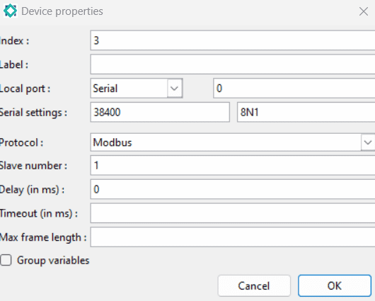
The following fields are available:
- Index : slave number. Each equipment is marked by a unique number.
- Label: text that only serves as an aid to understanding and has no impact on the operation.
- Port : type of port. You have to choose between Serial, Ethernet, Wi-Fi or Radio. For a serial port, you must specify the port number, the speed and the communication format. For an Ethernet or Wi-Fi port, you must specify the IP address of the slave. For a radio port, you must specify the frequency channel.
- Protocole : protocol to communicate. You have to choose between Modbus (it is the standard ModBus), Sirea (it is the extended ModBus that can be used only with Sirea devices), Modbus (inverted words) (the words that constitute long integers and floats are inverted compared to the standard Modbus), Modbus (multiple writings only) (used for slave 0 to send frames in broadcast to all the slaves) or Modbus (inverted words, multiple writings only)
- Slave number: Modbus slave number.
- Delay : interframe delay in ms of the communication.
- Timeout : time between the beginning of the wait for a response and the passage in error in order to continue the communication.
- Maximum length of a frame : maximum number of bytes in a frame, i.e. the number of words multiplied by 2 or the number of bits divided by 8.
- Group variables : check box that allows when reading data to create longer but less numerous frames by reading non-interesting data.
7.2 Declaration of variables
In the Declaration of variables, in the “Communication” tab, the “Remote address” field must be filled in with the slave’s address followed by a dot and the equipment number.
For example, if you write %MW16.1, this means that the master variable will be linked to the %MW16 variable of device 1.
In addition, in the “Communication” tab, it is possible to scale the value.
7.3 Communication status with the equipment
7.3.1 Statistical structure
There is information about the state of communication with the equipment. They are contained in a “LogStats” structure. To be able to read this structure, you must first obtain a pointer to the equipment and then obtain a pointer to the structure storing the statistics of the equipment.
Sirea has made available a whole library of function blocks that allow you to simply obtain the state of the communication.
Example to obtain the structure of the statistics of the equipment 1:
LogDevice *dev = LogGetDevice (1) ;
LogStats stats = LogGetStats (dev) ;
7.3.2 LogStats structure
| unsigned long lastTimeOK | Timestamp of the last frame OK |
| unsigned long lastTimeERR | Error on the timestamp of the last frame |
| unsigned char lastState | Status of the last frame (0 : no communication, 1 : communication OK, more than 250 : error) |
| unsigned long nbFramesOK | Number of frames OK |
| unsigned long nbFramesERR | Error on the number of frames |
8. HTTP Protocol
For a PLC with an Ethernet port, it is possible to develop a Web server with MicroHMI.
Two sockets must be used. The first is configured in COM_PROTOCOL_HTTP mode with its port 80 and the next is configured in COM_PROTOCOL_HTTP_QUERY mode with its port 81.
The use of two sockets allows for a smoother display and the correct loading of the images to be displayed.
If the PLC has an Ethernet port, if the HTTP option of the system code is activated, and if the application does not have an HMI, the Web server will be able to retrieve the files in the WWW directory of the SD card. It is enough to indicate in a browser the IP address of the PLC and the name of the file.
9. Wi-Fi
9.1 Mode
There is the Ad Hoc mode to make a Wi-Fi access point from a PLC and the client mode.
It is the %SW95 (W_MODE) variable that is used to manage it.
| Constantes | Valeur | Description |
| WSOCK_MODE_OFF | 0 | No WiFi connections |
| WSOCK_MODE_STA | 1 | Client mode connection |
| WSOCK_MODE_AP | 2 | Ad Hoc mode connection |
9.2 Useful features
void WSockSetSSID (char *ssid);
This function allows to initialize the name of the Wi-Fi station, both in client mode and in Ad Hoc mode.
This property can also be defined with the “W_SSID” parameter of the main.cfg file. The standard allows up to 32 characters.
- char *ssid : a string containing the SSID of the network.
Exemple :
WSockSetSSID (TP-LINK _ 9B4144) ;void WSockSetSecKey (char *key);
This function allows to define the security key, both in client and Ad Hoc mode.
This property can also be defined with the “W_SKEY” parameter in main.cfg.
- char *key : string containing the security key
Example :
WSockSetSecKey ("123456") ;void WSockSetSecType (char *type);
This function is used to set the type of encryption. It is particularly useful in Ad Hoc mode because in client mode it is enough not to call it to use automatic detection.
This property can also be set with the “W_STYPE” parameter in main.cfg.
- char *type : string containing the type of encryption. Possible values are “” (an empty string uses automatic detection), OPEN (no encryption), WEP, WPA, WPAAES, WPA2AES, WPA2TKIP or WPA2.
Example :
WSockSetSecType ("") ;void WSockSetKey (char *type, char *key);
This function allows to define the type of encryption and the security key. It is the equivalent of the WSockSetSecKey and WSockSetSecType functions.
- char *type : string containing the type of encryption. Possible values are “” (an empty string uses automatic detection), OPEN (no encryption), WEP, WPA, WPAAES, WPA2AES, WPA2TKIP or WPA2.
- char *key : string containing the security key
Example :
WSockSetKey ( "", "123456 ") ;10. Connection to a server
It is very easy to establish a connection with a MicroSERVER in order to retrieve data. The data to be retrieved must be configured in the “History” and “Remote server” tabs in the “Variable properties” tab in the variable editor. This communication can be done by a serial port if there is a GPRS modem behind.
10.1 Setting
The settings window is accessible in MicroLADDER in the “Program” tab of the menu bar of the main window, then in “Device” then “Main Device”.
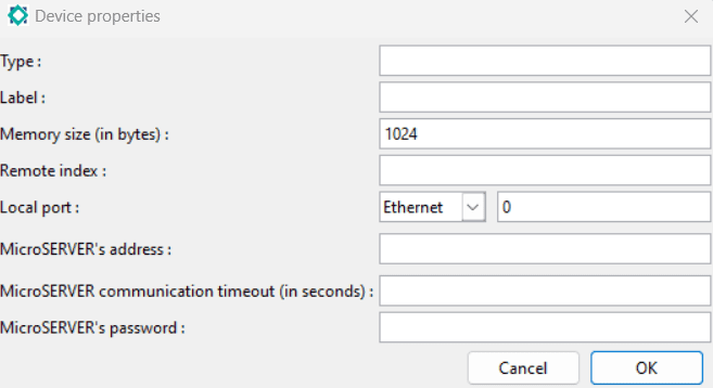
The parameters are identical to the use of the LogSetRemoteDevice function described in section 10.2 Setting by programming.
However, it should be noted that the “Memory size (in bytes)” field must be specified for PLCs that do not have saved RAM. The size of the RAM allocated to the storage of logs must be entered here. For PLCs with a saved RAM, all the RAM is used.
It is not necessary to specify the server port if the default port (13214) is used.
10.2 Setting by programming
void LogSetRemoteDevice (long index, char *type, char *label, unsigned char comPort, unsigned short speed, unsigned short format, char *host, unsigned short sockPort, unsigned short freq, unsigned long timeout, char *password);
This function is used if there are connection parameters that change during program execution. This function is active on edge. It is called only once or if the communication parameters change.
- long index : long integer indicating the index of the device that wants to connect to the server.
- char *type : string containing the type of device. This information is only used to perform the display on the server.
- char *label : string containing the label or location. This information is only used to perform the display on the server.
- unsigned char comPort : identification of the communication port used for the communication.
- unsigned short speed :indication of the communication speed. For Ethernet or Wi-Fi communication, it is necessary to set COM_SPEED_NONE.
- unsigned short format : communication format. For Ethernet or Wi-Fi communication, it is necessary to set COM_FORMAT_NONE.
- char *host : string containing the server address.
- unsigned short sockPort : port of the remote server. By default, this is port 13214.
- unsigned short freq : identification of the radio frequency when using lora.
- unsigned long timeout : unsigned long integer containing the waiting time in seconds.
- char *password : string containing the password.
Example :
LogSetRemoteDevice (850, "Gestionnaire", "Castres", COM_PORT_SOCK3,
COM_SPEED_NONE, COM_FORMAT_NONE, "194.117.213.206", 13214,
RF_FREQ_NONE, 60, "mdp");
LogSetRemoteDevice (850, "Gestionnaire", "Castres", COM_PORT_SER2,
COM_SPEED_9600, COM_FORMAT_8N1, "194.117.213.206", 13214, RF_FREQ_NONE, 60, "mdp");
It is not necessary to set the protocol of the Ethernet or Wi-Fi socket because the function does it itself.
To know the state of the connection, you must test the “LogDataPortStep” variable. It is greater than or equal to “LOG_DATA_PORT_STEP_WAIT_CMD” (value 6) when all is well.
The connection parameters are saved. It is not necessary to restart the LogSetRemoteDevice function each time the application is restarted, but only after a load.
11. Log management
On all PLCs, it is possible to manage the history. If there is no RAM saved, the data will be lost in the event of a power cut.
It is possible to have events (memorization of all the dates of appearance and disappearance of the breakdowns, memorization of all the dates of appearance of the messages), alarms (recovery of the present defects and the date of appearance) and traces (with dates and values of a data).
This information is stored in memory. It is then possible to read these data and save them on the SD card or the USB key. It is also possible to retrieve this information from an external system using a specific protocol.
11.1 Setting up the log
The parameters can be found in the ” Logging ” tab in the ” Variable Properties ” window of a variable.
11.2 Alarm
You can create an alarm for this variable by filling in the following fields:
- Alarm condition : drop-down menu allowing you to choose the logical operator for the alarm condition (<, <=, >, >=, != and ==). If you choose “None” then there will be no alarms for this variable.
- Alarm threshold : value of the condition with which the alarm is activated. An alarm is a condition, and an event occurs and is created whenever a threshold is exceeded.
- Alarm appearance label : text that will appear when the alarm condition is present.
- Alarm disappearance label : text that will appear when the alarm condition disappears.
11.3 Event
You can create an event for this variable by filling in the following fields:
- Event condition : drop-down menu allowing you to choose the logical operator for the event condition (<, <=, >, >=, != and ==). If you choose “None” then there will be no event for this variable.
- Event threshold : value of the condition with which an event will be activated.
- Event label : text that will appear when the event condition is present.
11.4 Graph
For this variable you can fill in the following fields:
- Logging type : drop-down menu allowing you to choose how you want to archive the value curves over time. There are three types of logging :
– “None”: no logging performed.
– “Standard” : takes a value with a regular interval
– “Averaged: takes an average value over a given period of time - Logging time (in seconds): logging time. It depends on the type of logging among two possible ones:
– “Standard” : specified time (1 minute for example)
– “Averaged”: specified period of time - Logging threshold : threshold beyond which it will record a value.
For a graph data to be stored, the elapsed time must be greater than or equal to the set time and the delta value must be greater than or equal to the set threshold.
In the case of a non-averaged value, at the end of the period, if the delta of variation exceeds the hysteresis, this value is recorded. In the case of an averaged value, an average is carried out during the period, at the end of the period, if the delta of variation exceeds the hysteresis, this value is recorded.
LogVariable *LogFindVariable (char *address);
This function allows to point to the “LogVariable” structure of a log variable. It must be used before performing an operation on a log variable.
- LogVariable * (return value): variable of type pointer to a LogVariable structure.
- char *address : string containing the variable.
Example :
LogVariable * var = LogFindVariable ("%MW20 ") ;LogVariable *LogGetVariable (unsigned short index);
This function does the same thing as the LogFindVariable function but from the index of the historical variable. The indexes to use this function must be known, but the indexes are assigned at compile time and therefore unknown when the program is written.
- LogVariable * (return value) : variable of type pointer to a LogVariable structure.
- unsigned short index : index of the log variable.
Example :
LogVariable * var = LogGetVariable (4) ;12. Miscellaneous information
12.1 Available memory size
Each declared variable takes up space in RAM. If this variable is also initialized, it takes up space in flash memory.
To know the amount of memory used, you have to look at the file “size.txt” which is generated during the compilation. All values are expressed in bytes.
| Column name | Meaning |
| text | Program code size |
| data | Size of initialized variables |
| bss | Size of uninitialized variables |
| dec | Memory size (program + variables) in decimal |
| hex | Memory size (program + variables) in hexadecimal |
| filename | Name of the file |
The sum of the data and bss columns must not exceed the size of the RAM.
The sum of the text and data columns must not exceed the size of the flash memory, knowing that 64 kB are already occupied by the monitor.
Example :

When the PLC has a saved RAM, the PLC variables (%M,%MW, …) are stored in this saved RAM and the compiler does not control the size. There may potentially be a memory overflow, but the saved RAMs of the automata are still quite large.
To find out if there is any space left in saved RAM, one solution is to declare a saved variable and look at the number of points that can be logged (see section 11. Logging for more details).